Happy Birthday RV-10 project!
I received my empennage kit exactly a year ago, so happy birthday unnamed airplane! I knew this was a long term project and had tried to envision what it would look like after a year. When I was building the benches and trying to explain to my neighbors that I was building an actual airplane in the garage.... well it was a somewhat comical conversation and their reaction is probably typical to most non-aviators.
I'm extremely happy with the progress I've made. I had a self imposed timeline of about 3-5 years but now I'm optimistic and thinking more along the 2-3 year time frame. I don't stress about the time that it's taking me. As a first time builders there is a lot I don't know. Self imposed timelines cause you to build when you don't feel like... which is more like a job than having fun. This is a bit of a shift from when I starting but now I build when I want to build and am fine if there are weeks that I don't touch the project. Consistent progress is better than rushing through things and inadvertently making mistakes.
Being a detail oriented project manager type by trade I really like to get into the weeds and figure out as much as I can upfront. Initially I was worrying about what switches I was going to use before I made my first piece. It's important to think about these things but the project will constantly change throughout the process. I tend to work through one kit at a time thinking about options on that kit and then the next kit as you move through it. Even with having the structure 90% complete I'm still unsure of certain aspects of the engine, avionics and interior.
All in all I'm having a blast and learning a ton. The constant learning is what makes a project like this so rewarding.
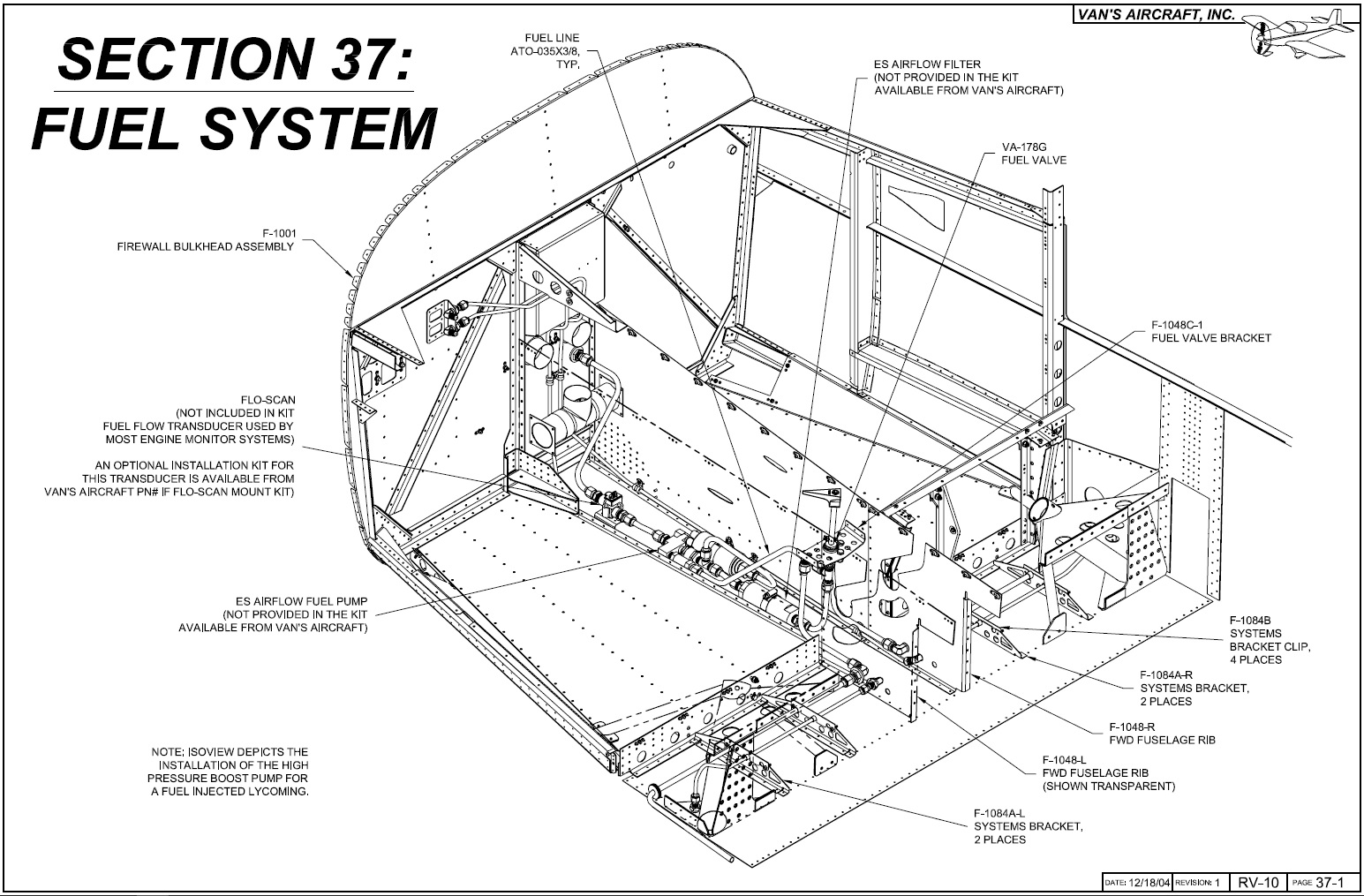
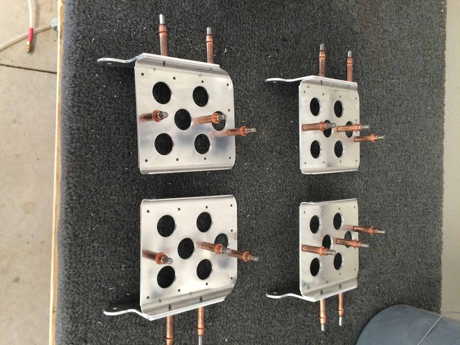
Fuel System
 |
| Section 37 |
As with the brake lines Tom at
TS Flightlines not only provided me with high quality stainless steel lines but helped answer questions and concerns that I
had. Going off his and some other suggestions I decided to put the fuel flow totalizator on the engine (When I get to that part) and used Air Flow Performance (AFP) filter and pump with an Andair Fuel valve.
As a first time builder some of these lines can be a bit confusing on which lines go where. Had to confirm with Tom that they went where I thought they went, I was right so that's a plus! Installation was fairly easy, I used some bushings from ACS for both the brake and the fuel lines under the seat. Had to remove some material from the brackets just to ensure a snug, but not too snug fit. Also hope I'm tightening the NTP fittings correctly, hand tighten and go about an extra half turn.
From under the seat the lines connect to the fuel valve. I went with the Andair because of the higher quality and that I will end up using an extension pieces for the arm rest that will eventually be in place. The factory bracket doesn't fit which requires you to make your own. Using the original as a template it's fairly quick work.
The lines then run to the Filter & Pump assembly. The plans call for these to be offset a bit but they can be connected reducing a few possible leak points. UPDATE: Removing this once installed through the access panel is very difficult. At first fuel filter check I ended up putting the AN line between the pump and the filter. This allows me to loosen the end nuts and a single clamp to remove the filter entirely.
Using the factory mount it secures down enough not to shake too much. Nothing magical but it all aligns well with the mounting brackets installed with the QB. The rest of it is just attaching the rest of the lines.
That's it for the fuel system until you mount the wings and install the interior.
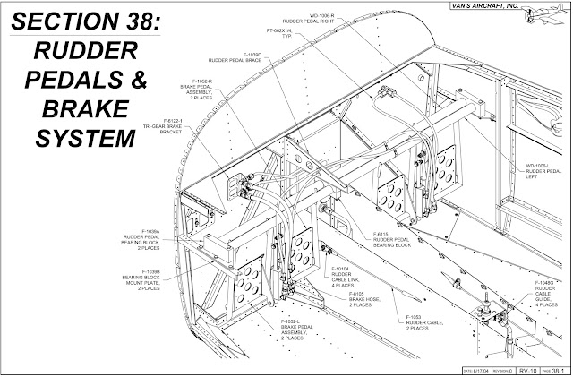
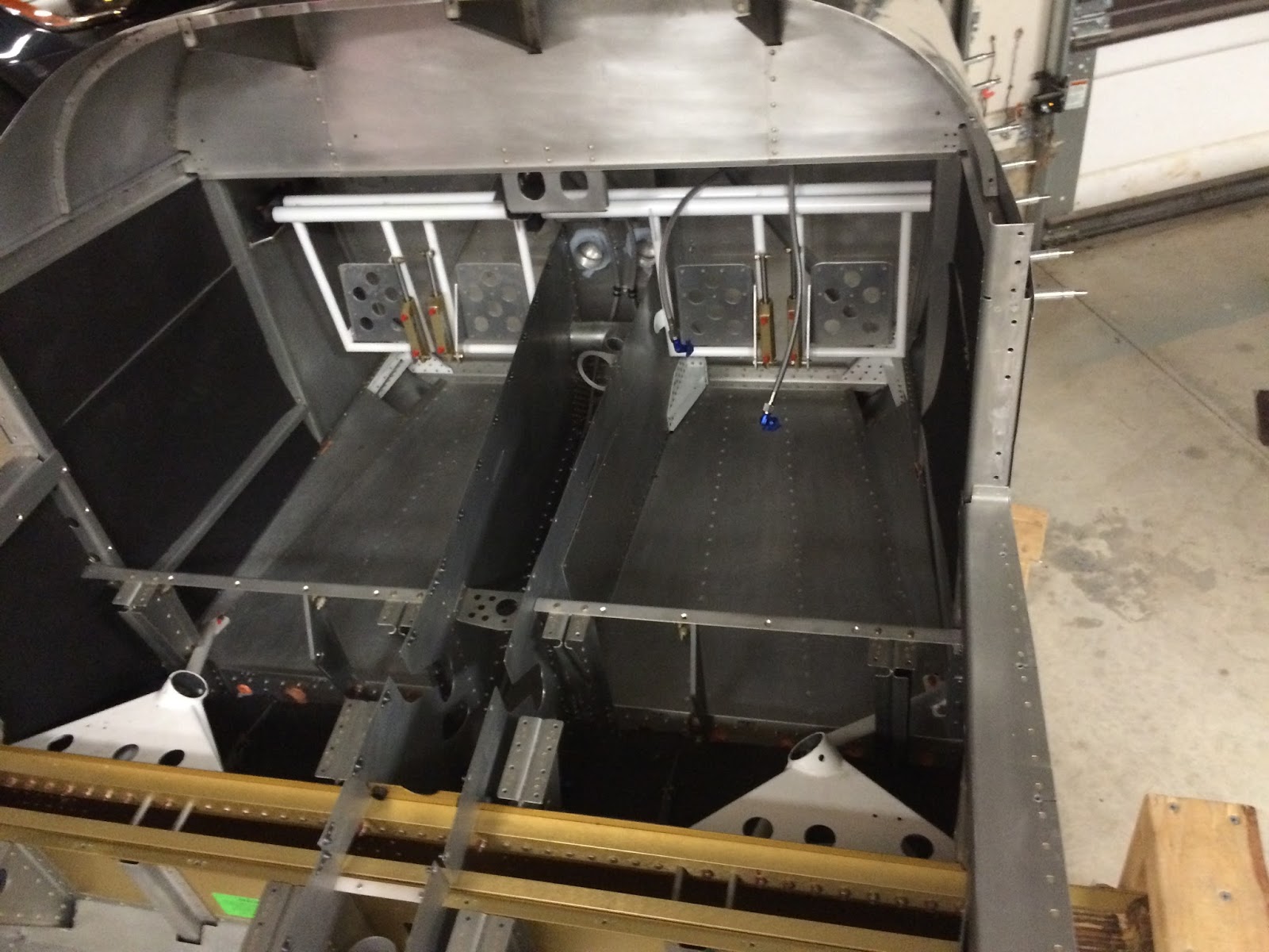
Rudder Pedals & Brake System
 |
| Section 38 |
Since I was going with the factory standard pedal set up I to actually back order these since I removed them from my original kit. Lesson learned is don't try and anticipate when an after market product will be available. Go with what's available at the time. This would of saved me a few hundred dollars because Vans punishes you on back-orders by not giving you the original Kit pricing.
Putting the pedals together is straight forward. There is a choice you have to make on which side you want the shop head of the rivets on. Overthinking a bit about traction I decided to put the shop head on the part where your foot is and the 470 manufacture side on the back. It apparently doesn't matter and some people actually use flush head 426s and countersinks the pedals. I also decided to leave them unpainted, thought about getting them powder coated but I would guess no matter what you do these are going to get beat up from flying so just left them be.
I finally bought a drill press because this section involves drilling very straight holes. In the past I did it with a level and my eyes to some goo success, however going a few inches concerned me a bit more. So with the drill press I was able to make the required brackets and get the pedals mounted in the plane.
One aftermarket item I picked up were some rudder cover kits. You can shape them any which way you want, some leave them square, I've seen others shaped as ovals and I decided to just round the edges a bit. Then used my drill press to make the holes. Attached them via pull rivets to not risk damaging anything with the bucking bar on the back in. Gives it a more clean look. Am debating on installing a set up front, that's going to be covered with interior so might not be worth the hassle, can decide later.
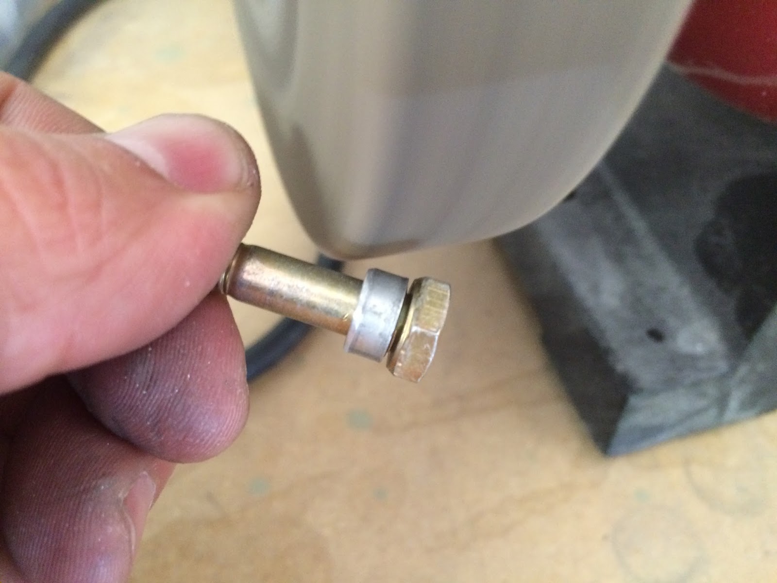
The last part I needed to finish was the
Airward RV-10 parking brake. I've seen some people make their own brackets or mount it in a different area, I decided to get the entire kit and mount it as suggested. I sent the below picture to Dave at Airward to make sure I had it installed correctly prior to riveting it to the firewall and finalizing up the lines.
Above is the completed rudder and brake setup. Now I haven't finished the brackets to connect the rudder lines to the pedals. I am going to wait until final rigging to work through that to make sure the rudder is straight with the pedals even.


