 |
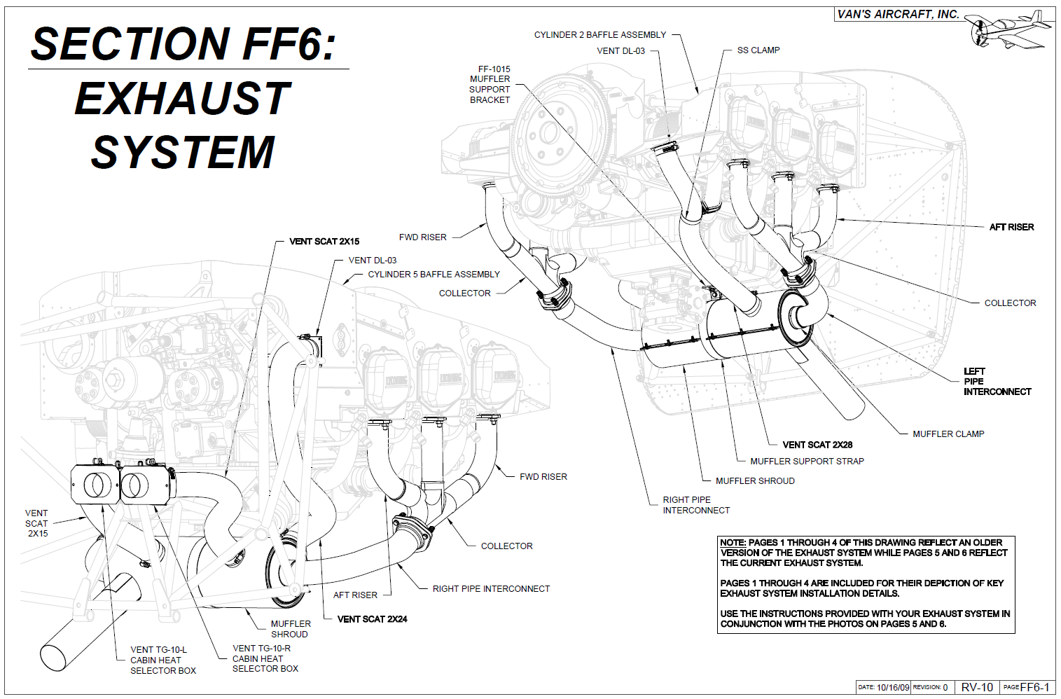
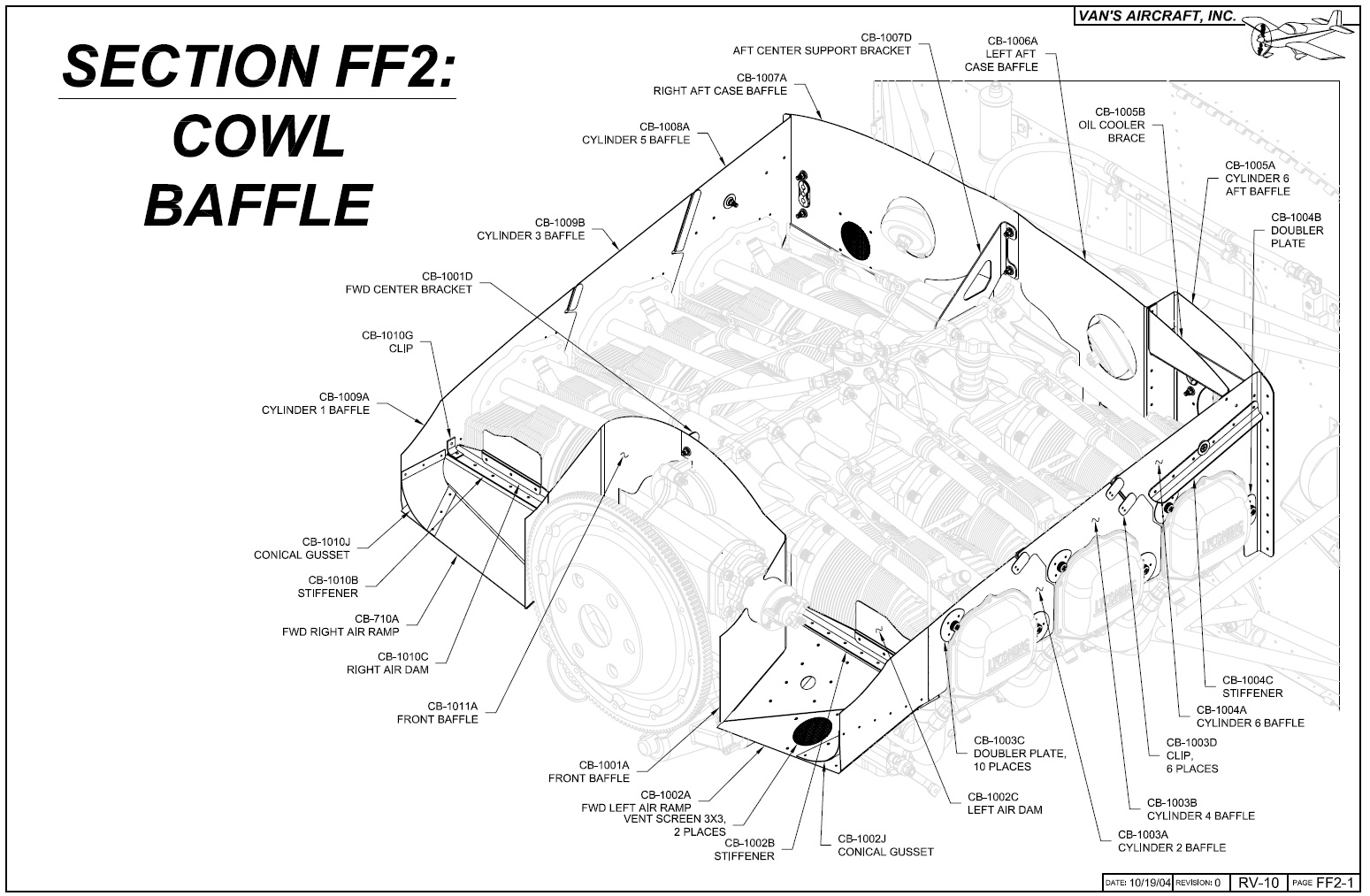
| Section FF2 |
You have two routes you can go in terms of getting cool air to the engine. One is the use of a
plenum while the other is per the plans and essentially uses aluminium dams and a rubber type material to direct the airflow. I decided to stick with the later in effort to not over complicate things. Initially working through things was fairly straight forward. Its back to messing with metal and following the directions. Should note that I was doing this section concurrently with the cowl fitting because later in the process you need to start putting the top cowl on to achieve a 3/8 - 1/2 inch gap. I'll make that it's own section because that has been quite the process.
Once you have the gist of the pieces put together you start test mounting it on the engine. I went ahead and covered up cylinders 5 and 6 so I wouldn't scratch the valve covers. There's very little trimming required to get these all on. Cylinder 6 is tricky but once you figure it out it's a repeatable process to put it on and off. When I got to the pages on the inlet ramps that is where it stopped being straight forward and turned into quite the headache....
See I'm putting in an Air Conditioning which means I have a compressor located on the port-side of the engine. This prevents a per the plans install since the inlet ramp can't back downwards. I actually knew all this going into it so it wasn't a surprise. Once again I reached out to Greg for some guidance as well as checked out
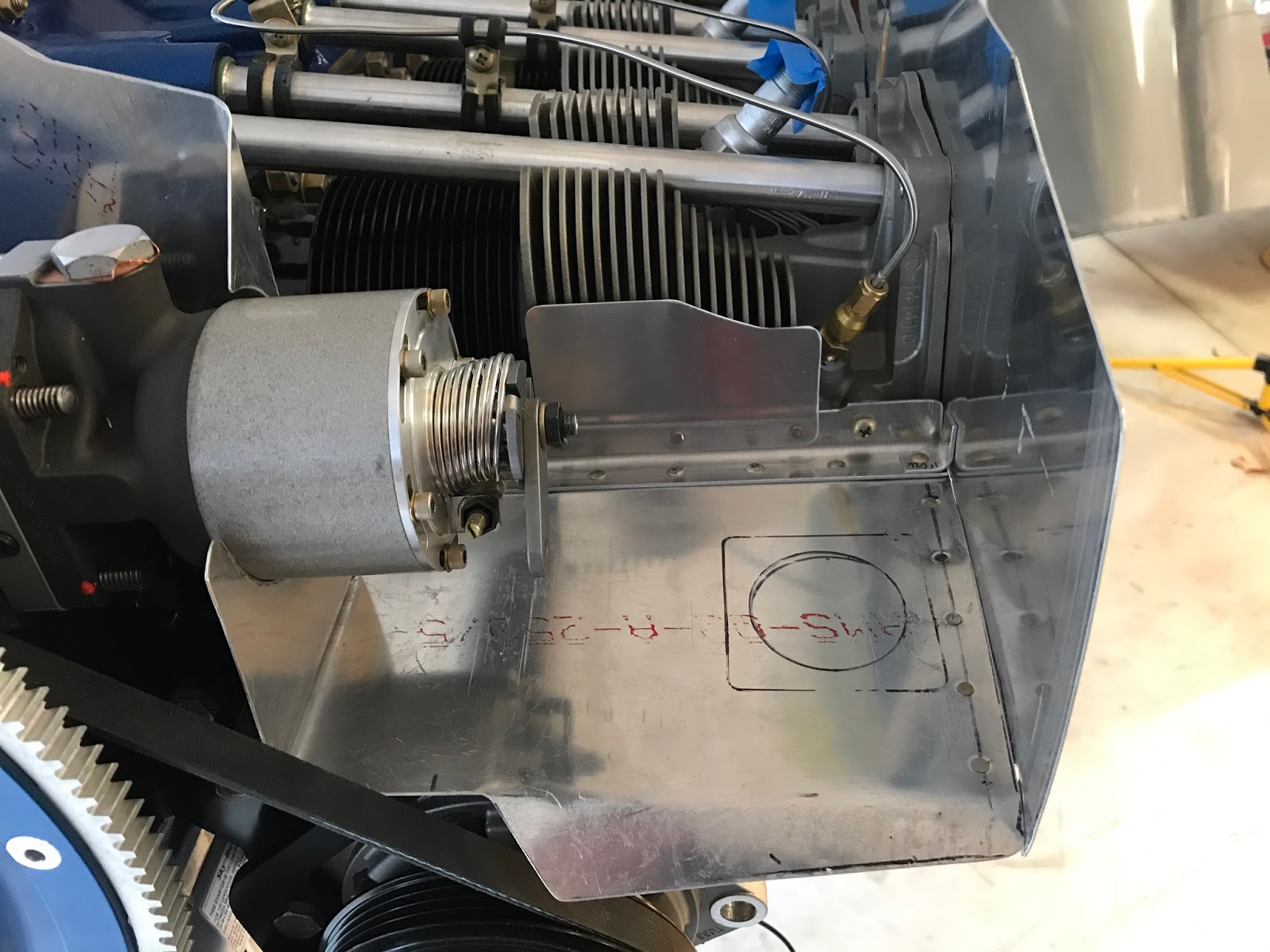
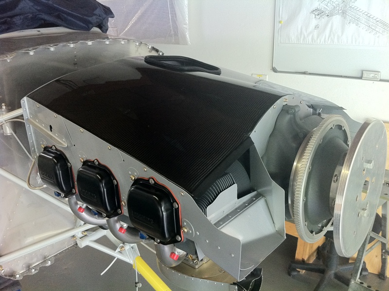
his install. If you look at his pictures he made a fiberglass ramp and keep the inlet ramp moderately flat so I followed suit... hence why I was needing to install the cowl and work the baffles in concurrence. Before I get into that, here's a nice picture showing the initial fit, when I still had the prop on.

I have a feeling each install is going to be a little different when installing a compressor and there are variances in height and pulley wheel position. I tried to keep at least an 1/8 inch gap between everything to keep things from rubbing. Also with the compressor there was a slight challenge getting the front ramp on and off with the governor on. So I had to loosen the bolts and remove it and then slide it back on to finish out the fitting. As you can see in the picture (which wasn't the final trim) that a lot of customization was needed. Especially in the piece around the governor where I used the stock piece but made new flanges and opened up the hole to fit. This is an early picture so it's before I really cleaned things up and made the hole for the exhaust cooler air.
After getting the inlets in place I began trimming the the baffle to get that 3/8 - 1/2 inch gap. I used the
paperclip method for that. You take a lot of material off, a little at a time. Once the top cowl was able to be reinstalled I focused on a section at a time. This allowed me to focus on ensuring I wasn't shifting the top and in turn the paperclips in any strange way. All in all I spent upwards of 4 hours doing this and that was even with some help.
With the final lines drawn I removed everything to make it easier to get a nice smooth consistent line. After going through and deburring everything in great detail I roughed up to prepare for paint. Obviously painting in an option but I like the look of a painted baffle, even thought I picked Aluminium as the color. Also want to make sure you get a paint that can withstand high temperatures, I picked an HVT product from my go-to online paint store
RE Paint Supply.
 |
| Paint drying |
Once everything dried I was able to get it all put back on the engine. This includes the governor that I had unbolted to get the custom ramp on and off. Really like the way it all turned out.
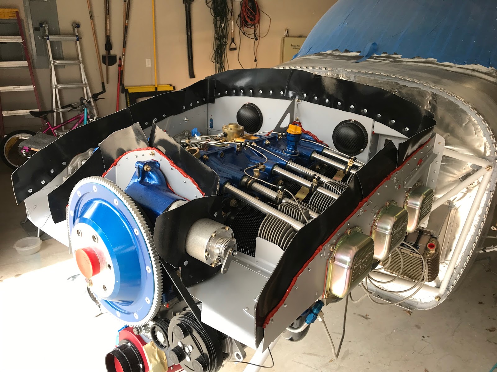
Following the experience of others I went a bit arts and crafts and made paper templates for the baffling material. I wanted to be able to cleco these on so I went ahead and put some 1" thick tape around the perimeter and drilled the holes about 3/8 down and spacing varied depending on the piece but was between 1.5 - 2". There's one spot over #1 cylinder that there's really not much material so the spacing is more like 3", just had to ensure good RTV coverage later on.
With the holes drilled I started making some templates out of construction paper. The idea was to have the more forward piece overlapping an inch over the next piece. Idea being that when air shoots in that it will help force the overlapping down, keeping air from escaping. With the paper in place I cut the top to have about 2.5 inches of material above the aluminium damns. This was to account for any variations post install, easier to trim than add.
 |
| Not pretty but serves the purpose |
Laid out the templates and started cutting the baffle material. Once cut I went ahead and drilled two of the cleco holes to get it in place and then using a reamer match drilled and cleco the rest. You need to use Acetone to clean the release residue from the baffle material to ensure good adhesion for later RTV application. Then it's just a matter of using the provided pull rivets and putting everything in place. After that it was fairly easy to give the material a hair cut to a consistent 2" per Vans suggestion.
Per the plans you have to apply RTV anywhere that air could escape. My previous work with RTV was out of a little 3 ounce tube which is a pain to work with, especially thinking about trying to run long beads with it. I picked up a can of
this which made easy work of it.
With the major work done I'm calling it good for now. I need to finish up the tension rods, which I'm replacing the stock stuff with 6-32 all threaded rod which is on order. Also need to reconnect the spark plugs and need to order the Ignition wire harness seals. Also anticipate some final trimming as I put the cowling back on, but no reason to go into detail on that stuff.


