Tuesday, January 12, 2016

Empennage Attach


Section 11

Project Punch List

If you've ever worked on a project you more than likely have used a project punch list.  It's literally a list of items that need to be resolved prior to project completion.  It's different than a plan because it's more reactive in nature and will vary throughout different phases.  This project comes with the plans and it's up to the builder to resolve and plan out some of the other items such as interior, avionics, lighting, engine ect.  I track that on a spreadsheet just tossing down ideas as I think of them or track parts, prices, ect.  But post EAA Tech Counselor visit it was apparent I needed to start up a list to track various items needing to be completed or fixed.  Even though I work in IT I'm very non-technical about my list creation and I use paper and a pen.  I used to try to get fancy at work with lists but I always reverted back to a pen and pad.  So that's what I'm doing now, using a list and marking off items as I complete them and if it gets too messy with notes I'll transcribe it to a new piece of paper.

Attachment

Going into this process it seemed fairly straight forward however it was anything but that.  I tracked my time but I can't tell you what I spent on the actual attachment steps, or what I spent fixing mistakes or working through my punch list.  I also didn't take a lot of step by step pictures because I would work sporadically on things as well as jumped around to various steps as I waiting to fix certain things.

I spent some time working through the previous punch list items as well as new ones that I found. For example for whatever reason I forgot two rivets on the HS Spar... easy fix but strange I missed them. I did the deburring of parts that I had missed or that were still a bit rough on the edges.  I went over each bolt that was permanent and ensure proper torque and marked accordingly. There were a number of rivets that I had put off fixing until now.  I had used a few of those 'Oops Rivets' which I recently ordered and they worked out great.  In one particular case I had to use a wood block and hammer to level out the skins before using the new rivets.  It's not the prettiest but looks much better and after paint won't be noticeable... plus it's on the bottom of the tailcone.

Elevators Attach

I had watched some videos of this process and the consensus what it's a bit of a pain.  You have to put them on, test fit, take them off, adjust, back on... ect.  It took me an extreme amount of time because I was chasing perfection.  The important part is you don't have binding and it's free to move up and down without rubbing or hitting anything.  There's also an aspect where you want to hang them so on the outboard HS edge and the inboard Counterbalance arm there is an even 1/8th inch gap.  This ends up looking somewhat like the picture below.
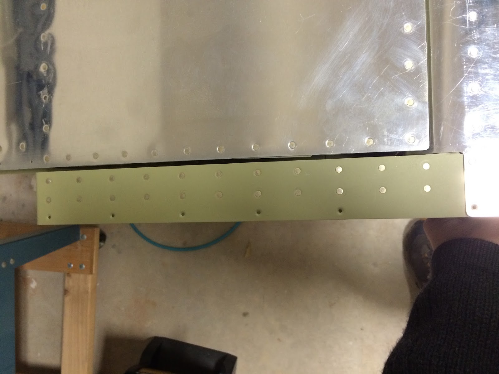

The problem is in this picture the right side is an 1/8th but the left side is 1/4th.  It was even worse on the right elevator with it about 3/8ths gap on the forward end.  This drove me crazy and I must of spent a good 4 hours putting these on and taking them off 70 or so times.


I finally got it to a point that I was happy with and decided to move forward.  The next step is to get the trailing edged even and they suggest using duct tape... I did that and also used a clamp on a specific rivet location (5th in) to keep it level.  Then you methodically remove the right elevator (again!) and match drill the left horn using a bushing that Vans provides... now like most I had to use a file to reduce it enough to fit but was easy enough.  After that you take the left elevator off and put the right one back on and drill that side.  Then you put everything together, lock the trailing edges and then using a wood block you made drill the bottom of the horns evenly.  There's an entire process to this to help ensure everything straight so it takes some time.


After working through all that you can once again check the clearances to make sure you have 35 degrees up and 25 degrees down.  All was well and decided to go to bed.

Well.... something was bugging me as I laid there in bed.  Grabbed my IPad and started some further research.  My main concerns were that if my counterweight arms were bent or warped and I was using that as the primary measurement then that would affect how each elevator was hanging.  The other concern was if they are uneven then that would affect the way it flies... which is bad.

After reading about some methods people used I decided to essentially start from scratch at midnight... after about an hour I had determined that I had the rod end bearing bolts on the inboard side too far out therefore compromising their strength and that indeed there was some unevenness on my counterweight arms.  I made a post on the Vans forum with some pictures of my concerns and findings.  The short version is you want to ensure your brackets on the HS Spar are straight (Look through them) and you don't want to deviate too much from the rod endbearings initial 7/8th inch positions and both elevators should be even.  Turns out my main concern with that 1/4" gap on the forward end of the counterweight arm is a non issue.  Per Vans it's there more to provide clearance to prevent ice build up if you get into those conditions... which as a pilot is a bad bad thing.

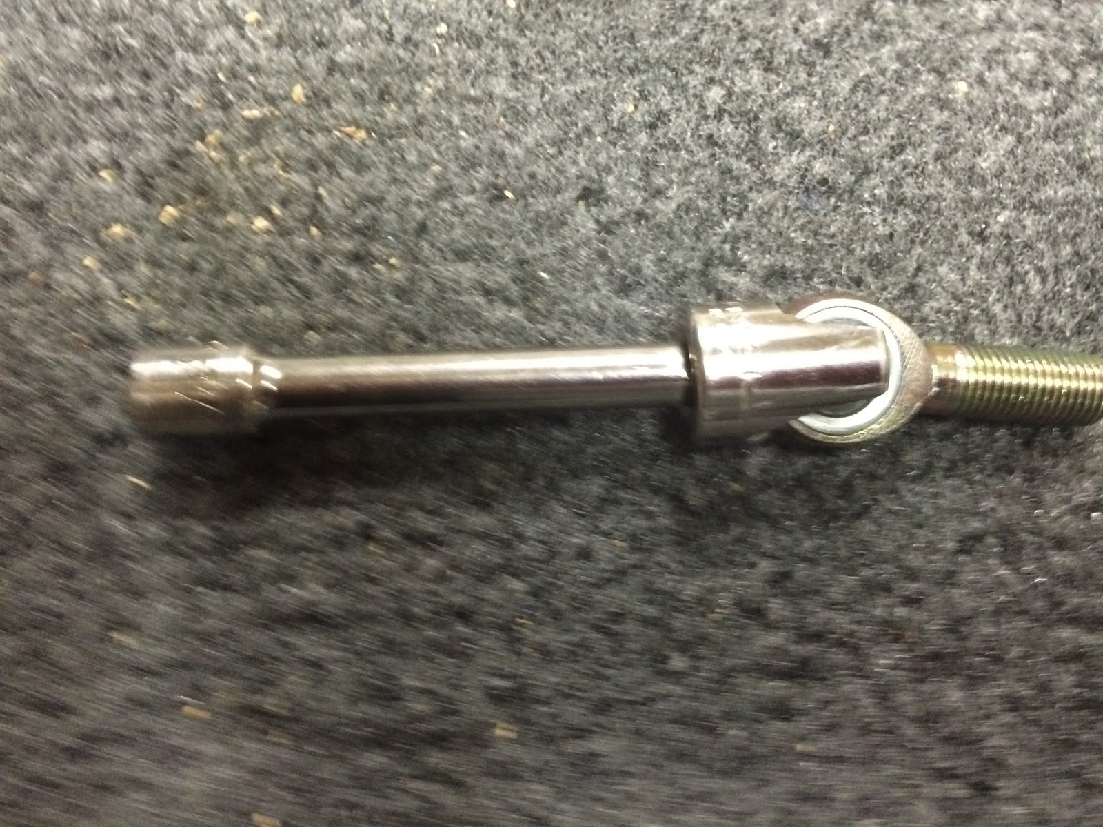
So I did three things to resolve this.  First I made a tool to make it easier to install and adjust the rod end bearing bolts.  I took an old socket and notched out the ends which worked out fine.  I've seen other people do it with PVC or you can buy a tool as well.

Next using the method I put on the Vans post I rehung and adjusted the elevators... Truth be told I found myself randomly walking out to the garage and readjusting a number of times over the course of a few days. The end result though I'm happy with, they're even, move unbound and there's no more than a 1/4" gap on the forward part.

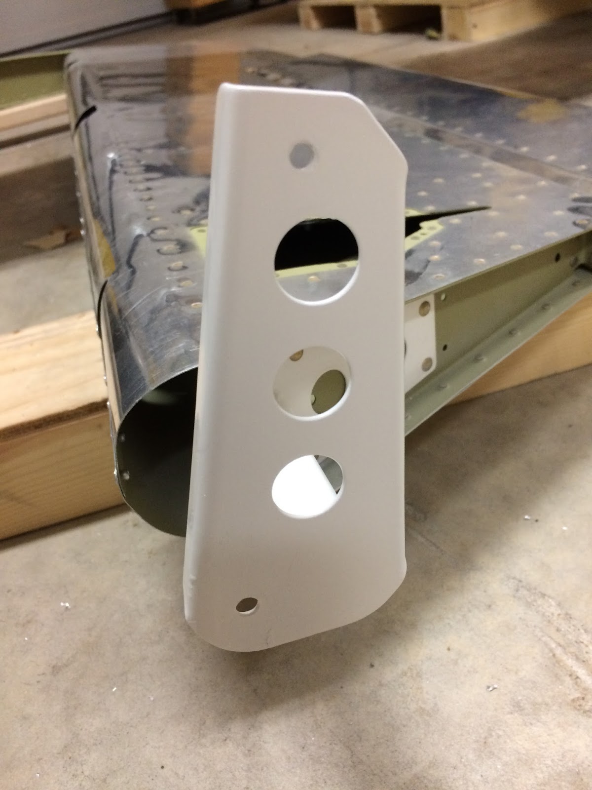
The last and most challenging thing was to get the extra holes on the horn welded in.  I got the information of someone who was able to help me get it welded... I did the grinding and he did the welding and turned out great.  Come to find out he's done a similar fix on someone else RV in the past.  I didn't take any pictures of the process, just wanted to work through it.  After they were welding and cleaned up I was able to redrill the holes in their new places following the same steps as before.  This time after I removed them I had to reprime and topcoat each horn since I grinded off a lot of the powder coating.  I'm not sure how prone these are to rust but if anything it was done more for aesthetics.
Redrilled and Primed
Rattle can white

Parts and Prime

I did a number of things out of order in this section. With my elevator horns messed up that sort of threw the linear aspect of the build off a bit. So not to just wait I jumped around and started making the brackets required for the HS mount and elevator trim set up.  It really helped out that the pictures in the plans were to scale so I was able to complete a piece, check it against the drawing.  I'm not sure what people use to get their parts looking like they were done with a CNC machine but mine are more of an artisan 'build a plane in your garage' type pieces.  I use a chop saw with a metal cutting blade, a band saw and a grinder.  It gets the job done but again not every piece is perfect for example on the HS shims one side of each is more rounded than straight.

HS Shim
Trim brackets

Trim cable brackets
Working out of order there were a number of other parts I deburred, drilled and cleaned so I could prime everything at once. It included the control arm that connects the elevators to the bell crank assembly, the elevator trim housing and some other minor pieces.  Using the last of my AKZO I primed everything, including the inside of the control rod.


Horizontal / Vertical Stabilizer Attach

This process was very straight forward per the plans.  In essence you line everything up according to a rivet point on the tailcone and ensure it's equal in distance.  You use a wood block to help keep it in place and then match drill.  Since this was the area where I added some additional depth to the bracket I ordered some longer AN bolts to use.


Likewise the Vertical Stabilizer was straight forward to attach.  Had to do some match drilling, it's also where I noticed I was missing two rivets... anyhow all fairly simple with the hardest part being that you have to fit your arm in a small space to get to certain bolts. There is a step to apple Anti Seize paste which may not really be needed now but for fun I applied it anyway.


Once you get to the step above you take everything back apart to deburr and clean up the pieces in preparation for putting it all back together.

Elevator / Rudder Attachment

Since you previously drilled and test fitting everything this step is a complete non-factor.  The only added challenge is getting your hand in the space under the VS to put the bolt, washers and nut on.


Likewise you have to have equally small hands to attach the rudder.  The good news is unlike the Elevators the Rudder went on without much adjustment. Took me about 4 tries to get it positioned correctly where when measured per plans was fairly accurate.  Final fit and measure can happen during rigging.

Elevator Trim and Control Rod

There are two components that need to be built in this section.  One is the control rod which is fairly straight forward.  Takes a bit because you need to prime the inside of it and give it time to cure completely before putting the ends on.  And with all my pieces in the tailcone I painted them as well.  Connecting it was straight forward but required you to make a wood triangle to position the bell crank in a particular position.  That coupled with locking the elevators in the trialing positions guides you to how much you have to adjust the control rod bearings.


The elevator trim actuator assemble takes a bit more time. Mine came out fairly tight taking a bit of force to make it move.  However once I hooked up the motor it really functioned fairly smooth when I hooked a 9 volt battery to it.


I bolted it in place in the tailcone but didn't run the cables to the trim tab.  Knowing at some point I'll be removing the elevators I will leave connecting this all together at a much later date.

This concludes the attachment section and will need to do a bit of reading before attempting the next section which deals with fiberglass.


Friday, January 1, 2016

EAA Technical Counselor

This year is off to a fantastic start!  Today was the first of what I hope to be many visits from an official EAA Technical Counselor.  I don't know if I'm lucky or if it's pretty standard fare but I was fortunate enough to have a total of three Technical Counselors show up.  I was extremely impressed with the experience and depth of knowledge these gentleman had.  Definitely a resource you should utilize when building your first, or even fifth plane.
The visit lasted about an hour and a half and included some official paperwork.  The rest of the time was going over the pieces and answering any questions that I had.  The most important thing was they said I am doing a good job and there were no major issues.  Here's are some items and pictures that may help someone on their build.

Riveting

Okay when it comes to riveting I am my own worst critic.  It's just not perfect and I want it to be perfect.  So when it's not perfect it bothers me, it really really bothers me.  My friends can look at it and say "Hey that looks great!", I look at it and I see all the little issues I know about because I did them.  They assured me this is completely normal, gave me some direction on how to improve a few of them and we talked about some of the techniques that show plane builders use to make thing 'perfect'.  In my case it's going to involve primer and paint in a few years.

Deburring

There are some areas on the skins that weren't deburred as well as they could of been.  My method was to debur enough that you wouldn't get cut.  Some of these hard to reach places just involve running a file over it a few times followed by a scotch brite pad and calling it a day.  I didn't do that well enough or missed a few areas.  For example in the picture below you can see it's had a pad ran over it but you can visually see it's rough.  I'm going to spend an hour or so and get these all cleaned up.


Cracks

Might a tad hard to see in the picture but I had a small crack in the skin.  This is what happens when you hit it with a wrench while taking on and off the elevators 30 times.  It's a tiny crack but if ignored can turn into a much larger crack similar to what happens when a rock hit your windshield.  The fix, oddly enough is the same as what you do with a windshield. 

To fix this I'm going to drill a 1/64th or so hole at the edge of the crack.  This will keep it from getting larger and then I'm going fill the spot in with some JB Weld.  Luckily I'm a pro with JB Weld so will not need any further instruction on that.


Bolts and Torquing

Over or under torquing bolts is/was a concern for me.  I have a pretty good torque wrench but new to such precision bolts I wanted to make sure I was doing it correctly.  What I learned is you find out the torque required to turn the nylon threaded nut and add that to the value.  So these AN3 bolts require 20-25 in lbs torque.  If the nut takes say 2 lbs of pressure to start turning then the range will be 22-27 in lbs.  So before I mark these I'm going to loosen them a bit redo them.  Not a ton of them so shouldn't take long and moving forward I know how to do it correctly.

Also the area where I added the additional 1/16th or so spacer needs the bolts replaced.  I up sized the rivets but used the bolts called out in the plans.  As you can see by the picture it's too shallow as you need a thread and a half at least clearance on the bolt.


Advisory Circular(AC) 43.13

Pilots know what an AC is and most will know that 43 deals with maintenance.  What I didn't know was AC 43.13 is a 646 page document that covers all sorts of building techniques. Specifically it's 'Acceptable Methods, techniques, and practices - Aircraft Inspection and Repair' . I went ahead and downloaded a copy and will start referencing it first when I have a question or need a better understanding of something.

In closing I can't stress enough how important it is to involve your local EAA Chapter on a build.  They're there for the same reason you're building a plane in your garage, a passion for aviation.  The reassurance you get that you're on the right track is priceless and having a team who wants to help you succeed in your project is also priceless.
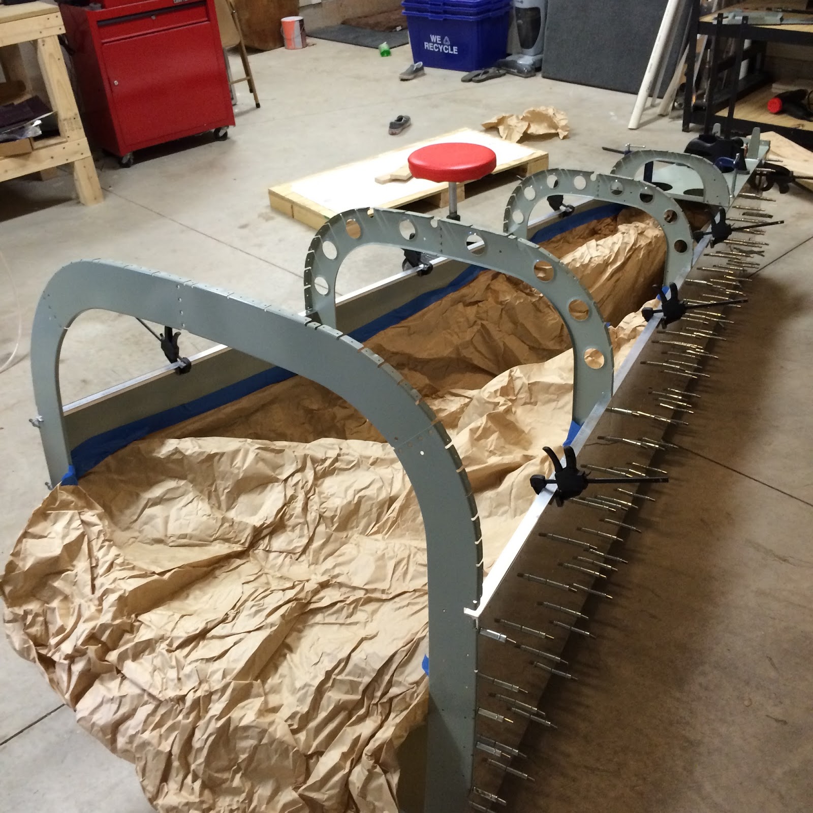

Saturday, December 26, 2015

Riveting Holiday fun & Tailcone complete (For now)

Page 10-20

Riveting

Looking at page 10-20 (shown above) of the plans I knew this was going to be a time-consuming process.  I anticipated about 15 hours to do and I was fairly close to that.  It's hard to determine exactly since I spent some time and focus on rematch drilling, priming and painting the Aft Deck, brackets, spacers, etc.  I was very methodical about this fix to ensure it's done perfectly, will show some pictures later.

My original idea on riveting was to back rivet the entire thing.  I have read about people doing that with some success and it seemed like a good idea.  I started out doing this, but I had some issues early on with the j-stiffener (F-1047) pieces and the bottom skin where the back plate wasn't at the correct angle and caused some skin dents.  There are specifically 4 rivets on the bottom that I'm not particularly happy with.  I went ahead and ordered some Oops Rivets from Vans.  These are in essence larger size 4 shanks but the 426 countersunk head is the same as the size 3 rivets.  My plan is to drill out the rivets with a #40 bit and then use the #30 reamer to enlarge the hole.  After that I will use a small block of wood, hammer and some dimple dies to get everything "flatish" and then rerivet.  And since I used rattle can paint I can paint over any inside scuffs fairly easy.

Since I was primarily working by myself I had to back rivet most the bottom.  When I got to the forward ends I was able to use a gun and bucking bar to do them.  Process is always the same, set 4 or so rivets in, tape over and drive each rivet ensuring the bar and gun stay in place.  The tape helps with scuffing or rivets shifting around.  I followed the directions minus riveting above the top j-stiffener since I will need to remove the new longerons to countersink later.  I chose not to do this after I match drill since I had to redrill the aft deck.  Didn't want to introduce any new variable that could cause something not to sit right.  Should also mention I didn't dimple the top row of the side sinks either for the same reason.

Bottom Rivets
After the bottom was riveted I moved onto the bulk head flanges with a gun and bar.  Again, working four at a time and alternating sides to get everything set in place at the same time.  I'm not sure if it would matter if you one side completely first and then the other... but didn't want to risk anything.  I also started with the middle bulkhead.

After that it was just a series of riveting different things at different times per the plans.  The sides were almost primarily buck riveted.  There are a few towards the end where you are able to use the pneumatic squeezer though.

In progress picture
Bottom again
Finished Tail
Page 10-21 is putting together the Bellcrank Rib assemblies and then riveting those into the tailcone.  The biggest challenge of this was actually riveting them inside the tailcone.  I decided to use the gun and a bucking bar for this step.  My arms were just long enough to drive the rivet from the outside while holding the bar in the inside.  Gravity helped a bit and while riveting I was resting the bar on the rib itself, so I could use two fingers to hold it in place.  As with all the steps you don't mess with anything that involved the front rib (F-1006).  All that will get dealt with when you tie the tail to the fuselage.


At this point I was done with riveting until I could complete a few steps with the longerons. But before I could work with that I had to redrill the Aft deck.  This involved Cleco'ing the tops back in place for rigidity and much like previously use paper to catch all the shaving inside.  I used a number of clamps and a level to make sure nothing was out of alignment and match drilled away, clecoing as I went.


F-1011D

This piece caused me some severe anxiety! This was the part that I didn't do correctly the first time around and ended up having to replace a total of 6 pieces.  I'm happy to announce it worked out great and I'll not have to worry about it again.  Also, the bonus as I mentioned before is I think my longerons fit better this go around then they did before... could just be that I'm being an optimist though.

Left- Old Bracket... Right - New Bracket
Triple checking longeron coverage
Really locked this piece down prior to drilling
Final result

Finishing up

I spent a few hours Christmas day removing the longerons and brackets to prime.  It was in the 60s and we had cold and rainy weather in the forecast, so this was really my only chance to get this done.  Prior to doing that however I had to countersink the 3/32 holes on the longerons and a few other minor items.  Everything worked fine, and I was even able to top coat with some rattle can paint later in the evening.

This officially retires my homemade empennage box paint booth.  This thing worked out great, small pieces I put on the wire mesh, larger pieces I set on top and if I had a lot of pieces just laid some cardboard out and set them in the middle section.  Since I'm doing QB Wings & Fuselage that get primer washed at the factory I won't be applying AKZO to anymore extremely large pieces.  For the remaining smaller pieces I plan to use the rest of the AKZO then switch to a rattle can primer and do it all on some cardboard.

Before
After
Even though the new parts were fully cured I decided to move forward.  Since there was little chance of things getting scratched it wasn't much of an issue.  Once everything was cleco'd in place it was just a matter of riveting the various rivets of the aft section.  I went longer on the spacer section since I added some depth to that piece.  Instead of using -8 rivets I used -9 which measured out correctly per my rivet gauge.

Really the most challenging part of finishing the aft section and the bell-crank assembly was finding the right hardware.  I had to use my go to reference book and micrometer to measure the bolts out.  It didn't specifically state in the plans, but I did go area and torque everything out to the proper Inch Pounds for the bolts; 25 for AN3 and 50 for AN4.

Aft Deck
Battery / Bellcrank assembly
Close to 200 hours into the project and I have all the empennage pieces completed.  I won't rivet the tailcone tops till I'm close to being complete, not wanting to crawl inside the tail cone if I can avoid it. 

I feel like I'm making good pace and with about 3 months before I get my QB Kits I don't feel rushed on the build at all.  Prior to assembling all the parts into an actual empennage I would like an EAA Tech Counselor inspect all the pieces. I'm sure given what I've learned over the last four months there are areas and rivets that need some attention.

Neato!

Sunday, December 20, 2015

Tailcone Reassembly, Gap Fix and Longeron Redrill

Sub-assembly Riveting

Had another warm day this week so was able to go out and prime the skins pieces.  That leaves me with probably just enough AKZO to prime my replacement longerons and brackets.  I also used another 2 cans of paint so went ahead and ordered another case (6).  Since I knew I was tight on paint I wasn't able to paint the top skins, which is fine I can do those later and will just need to rough up the AKZO a bit to ensure adhesion.

In between the priming and paint curing I started riveting the sub assembly pieces.  I had missed previously where I was supposed to countersink some holes on the bell crank assembly. Wasn't a big deal, just went ahead and made my countersinks and then repainted over the holes prior to riveting.


The next part is just a matter of riveting up some of the bulkhead parts, attachments and ribs. Was able to use the pneumatic squeezer for a majority of the rivets which made it easy and uniform.


To reassemble you just follow the process like before, the only tricky part is getting the back bulkheads and tie down skin back in.  The below picture is before that step.


Gap Fix

Because on my previous foul up with the longerons I needed to remake the F-1010A horizontal stabilizer attachment angle. When match drilling back onto the F-1010 bulkhead my clamps didn't hold tight enough, and the middle hole was a bit lower than I wanted.  I didn't know how much of an issue this would cause so I went ahead and match drilled the rest with a solution in mind if it was too low.

After clamping the new longeron pieces in place there was a substantial gap between the bracket and where the longerons needed to sit.


I tried to fabricate a part out of the 'Empennage Trim Kit' pieces provided by Vans.  They're pretty thin so it wasn't as snug as I wanted.  So instead I drew out the size of piece I needed on some scrap ie previously messed up parts.  Cut this out and worked on the sizing to get it to be as tight as possible so once bolted/riveted it won't move.  After putting the spacer (Also remade) on top I was extremely happy with the results.


No Gap!

Longeron Redrill

Ever since I botched up my old longerons I was logistically trying to mentally work out the fix. On one hand you don't want to enlarge the pre-punched holes and on the other you don't want to throw off the alignment with the new parts.  The plans call for drilling with a 3/32, cleco'ing the bottom skin, then when you get the top skin on match drill with the #40.  This insures it's a tight fit.  However after talking to Vans they just suggested I do it this time with the #40.  I assume this reduces the risk of messing up the pre-punched holes.

I hate to say it but my new longerons are a better fit than my first ones.  Cleco'ing everything up I tested the alignment of the tail... it was 2 10ths of a degree off.... but so is my floor so I'm calling it level.


Because of the amount of material you're removing from the longerons there's a concern with metal shavings.  First go through it's a non issue because you take everything apart again.  This go around I'm not so my solution was to tape some packing paper in the middle to catch the shavings and prevent them from getting stuck.

Now after drilling I removed the longerons to deburr and ran an old t-shirt on the skins and visually inspected each side.  This also knocked more material onto the paper which was easily removed and discarded.  There was one spot in the back I didn't cover well enough but was able to uncleco and work the shavings out with the t-shirt and air compressor.

Ready for Surgery
Redrilled, Deburred, Cleaned and Back together... success!
With the Aft Deck cleco'd on.
My plan is to get a majority of the structure riveted up before placing the top skins on and redrilling the deck.  Since this is were I fouled up before I want to take my time to ensure no mistakes this go around.  I'm also waiting on the bracket piece I ordered, said shipped on the 10th but no status update so guessing it hasn't shipped.  Will probably just order the aluminium and make it myself again... but this time correctly.

Tailcone Riveting

Now starts the long process of riveting the stiffeners and bulkheads to the skins, in turn completing this major section.  This is the first time in the build that it's truly a two person job.  I've seen where people have riveted the bottom by removing a side, then riveting the two sides but my concern is alignment so would rather rivet it while it's all assembled.

My approach is similar to what others have done and that's to back rivet the entire thing.  Back-riveting ensures you're pushing the parts stiffeners and flanges in when riveting, also gives a much cleaner look on the outside.  The downside is it's a bit of a process to do this and defiantly requires two people to move this piece around.

Experimenting with different processes I was able to get one full stiffener riveted and part of another.  The rivets look great but it's going to be very time consuming.  I've read people spend 15 hours or more just on this step and can completely understand that.  My way forward on the bottom skin is to put each cleco in from the inside out, tape a line of rivets and then move the bucking plate along the bottom doing 6 or so rivets at a time.  The second person is required to help not only move this piece around but angle it during back riveting to ensure it's flat against the plate.  This is going to be especially crucial on the curves of the flanges.


Sunday, December 13, 2015

Tailcone Prime and Paint

One thing that I'm doing different on the tailcone versus the other empennage parts is that I'm painting the parts after priming.  Aesthetically I would prefer to see a clean color when looking down the tail vs AKZO primer green. Also, as I continue with this build I may scratch, add or remove parts and wanted to have an easy method for doing touch ups.  With the easy part in mind I picked an off the shelve Rust-Oluem product as a top coat. There are a number of colors and I picked Light Machine Gray because it's fairly neutral and I'm planning on a gray and charcoal interior so it should blend well.

With the current weather starting to get cooler I wanted to get a bulk of my tailcone parts primed and painted over the weekend.  Saturday it was warm enough to paint but with a threat of pending rain I had to plan accordingly.  I laid out the parts in my garage and did my usual routine of prepping the parts and letting them dry.  Once I was a few hours into part prepping I mixed a batch of primer and started with thin coats, 2 each side.  A few times drops of rain started to fall so I pulled everything back into my garage, dried pieces off and started again.  The rain wasn't falling consistently so was able to get everything primed over the course of the afternoon.

Organized parts, I labeled the cardboard instead of the parts.
Primed Parts, at the point I label the parts.
You have a window of time between priming in which you need to paint to ensure proper adhesion. AKZO states that time as being 3 - 24 hours.  So even though today it was in the 40s and really too cold to paint outside I had to get it done so decided to do it all in the garage. I set up my paint booth and laid out several pieces of cardboard.  Put my shop fan facing the work area and laid everything out.  To prep each piece, I visually inspected for any issues and used 600 grit sandpaper to sand any areas of concern, then used a clean rag to get any dust or particles off.

Painting was time consuming but not difficult.  I used a little $5 handle that hooks onto the rattle cans to save my fingers.  Worked out well and put 2-3 coats on each piece.  After letting it dry for an hour or so I flipped the pieces and repeated the process.  After an hour or so of that I visually inspected each piece and touched up as needed.  My garage is insulated but it's probably still 60 something in there so I'll give the pieces a few days to cure before I mess with them.

A few of the parts painted
Went through almost 5 cans!
Once I finish dimpling the skins I will repeat this process with them.  I will also have to do this with my replacement pieces that I should get in the next week or so.  Given that it will most likely be cold out I will need to do this in the garage again.  Wasn't much of an issue, important to wear a respirator and periodically open the garage doors and let the paint dust blow out.

Wednesday, December 9, 2015

Vans Diagnosis....

There is a feeling of wanting to quit when things go bad.  You shift from the mentality of "how do I resolve this?" to "how do I get out of this?".  In Physiology they call it 'Fight or Flight', in Project Management they call it things like 'Anxiety' or 'Stress Management'... call it what you want but it's a very powerful feeling and it's something I've been aware of since I was a kid.   My dad taught me back then that when you're working on a project (In that case a skateboard ramp) and you get to a point where you're annoying, angry or otherwise distraught about the project you're working on to take a break and come back later with renewed energy.

That's what I did, be it only 24 hours... that 24 hours was enough time for me to mentally grasp and accept the current position I'm at and look forward to what I need to do to resolve it.  Vans stance seems to be if there's any deviation from the plan the first step is to view what needs to happen to get it back to plan.  In my case these parts are all still loose parts so there's really no reason why I just don't replace the parts that have been impacted and move on with the build.  So that's what I'm doing.....

To correct this issue I need to replace the following;
  • F-1032-R Right Longeron
  • F-1032-L Left Longeron
  • F-1014 Aft Deck Vans said this can handle a few extra holes
  • F-1011D Attachment Bar Support Angle
  • F-1011B Stop/Doubler
And since I'll be redrilling through the Aft deck and it may or may not line up exactly like before I also need to replace
  • F-1010A Horizontal Stabilizer Attachment Angle (AA6-125X1X1)
  • F-1010B Spacer (AS3-125 x 1.000)
This comes out to about $50 in parts, since the longerons are well... long, shipping will be around $30.  So to get this back to plans it's going to cost less than $100 and add a few more hours to the build.  In the mean time I can continue, deburring, dimpling, priming and all the other fun activities that are involved with building an airplane.


Tuesday, December 8, 2015

Tailcone Brackets, disassembly and somewhat major issue

Tailcone Brackets

An item I left off on my previous post was having to create several brackets and do a bit of match drilling with the aft deck into the longerons and other pieces.  Making the brackets are fairly painless, just follow the measurements and trim accordingly.  The drilling however is a bit of a different story, maybe should have used a drill press or have someone QA my measurements prior to drilling but I messed up a set of holes on the F-1011D bracket.  In particular the holes that go into the longerons, but will get to that in a second.

See how the top bracket holes don't like up to the picture
Starting out with clamps in place and starting from the middle you start match drilling all the #30s in the order called out in the plans.  I was so focused on spacing the longerons correctly I overlooked that I had completely missed the center line on the F-1011D bracket.  Even looking at the picture now it sticks out like a sore thumb, probably because I know it's there.


After that I started the disassembly of the tailcone.  This is a methodical process making sure everything is labeled correctly and that no hole is left untouched or any pieces with jagged edges or otherwise unfinished looking edges.

Major Issue

While deburring the longerons I noticed that instead of holes where the F-1011D bracket is there were little notches instead.  I instantly knew where I went wrong, remeasured and found the problem.  


Solution #1 - Remake the bracket, replace the doubler, aft deck, both longerons and cleco the plane back together to match drill everything accordingly.  Time and cost aside this might lead to some enlarged holes or other issues such as fit with match drilling something twice which may or may not line up exactly as it was before.

Solution #2 - Call Vans!

Well that's only part of the solution and it's what I did.  Builder support requested I take some pictures and send it to them, so he can review it with their engineers.  The good news as I see it is the notch is only an 1/8 inch in... will be filled by a bolt and there's a lot of material in terms of doublers that will also help reinforce the longerons in that area.  Another positive is there's quite a bit of extra room below the longerons and in the bracket area that can be used to come up with some new methods to ensure proper strength in this area.

Shows the doubler and how the longerons line up.  Didn't include the Aft plate.
I will wait for Vans suggestion but here are some thoughts I have.  Always looking for the positive felt this would be a good time to work through some ideas.


This is actually upside down... 
Idea #1 - This involves making a fitted bracket which would be the thickness of the longerons to be sandwiched between the Aftdeck/doubler/bracket group and a new made bracket which extends beyond covering the entire bottom of the longerons.  This would allow the screws for the #12 to drive though the notches and be secured by the bottom piece which is all riveted to the aftdeck, doubler, ect.

Idea #2 - Same concept as above but involves instead trying to capture some forward rivet holes as well.  The concept is the same, first bracket is the thickness of the longerons.  The paper in the below picture represents a smaller triangle bracket which would capture not only the Aftdeck/doubler/bracket group but the first forward hole as well.  Could even throw in an extra rivet in the middle there.


Idea #3 - To me this one makes the most sense but may be a bit overkill... then again I don't mind overbuilding things, especially untested things.  This is similar to #2 but uses a much larger triangle bracket.  This bracket would capture the #12 hole, two Aftdeck/doubler/bracket group rivet holes, and two rivet holes on the longerons forward of the notch.  Could also add an extra rivet hole into the aft deck to keep the middle-sandwiched piece in line.


Will be continuing one with the next few pages of the plans until I hear back from Vans on a preferred method. They may have something completely different in mind and will defiantly post about the fix when I get it.