Friday, September 9, 2016

Control System

Section 39
If you're watching the time stamps of my build log post it may look like I just rocked through this section in a day or so... that's not really the case though. What happens is I become rather adept at multitasking and I might work on two or three sections at once. There are sections in the build that have little to no dependencies on one another for example fabricating parts or working on both the wings and the fuselage. Case in point I was working sections 37, 38 and 39 at the same time.  So in sense I did complete 3 sections around the same time but it took me a good month or so to do it.

A downside to this process is I tend not to take a lot of pictures or a picture of random parts at random stages.  For example below are some primed control rods,  idler arm assembly and some other various things.

After the above parts dried for a week or so I riveted the elevator push-rods in the same manner as I had done for both the wings and the empennage. The only issue is it seems no matter what I do in terms of tracking the parts and their orientation I always have to do a bit of reeming before I can rivet it all back together.  I don't know if it's the primer or maybe after deburing something gets skewed but I have yet to have one go back together without a bit of post primer work.  I don't actually know if these needed to be primed since they reside in the tunnel but the plans didn't use 'Prime if desired' verbiage and instead just said 'Prime'.  It's not that big of a deal so I primed them up.

The Idler assembly was entirely build by my neighbor Jason.  I showed him how to deburr, match drill and fabricate a part.  Actually had to fabricate the spacer twice because I wasn't happy with my first one, it was a bit narrow.  Decided not to prime this part since it's in the tunnel and will be easy to inspect and replace if some corrosion happens down the line.  One problem with the part is it was extremely tight once installed between the brackets and was rubbing against the brackets.


 Concerned about this I posted on VAF to see if anyone ran into this.  The general consensus was to remove some material on the back end so it can freely move.  Probably could of gotten away with a 1/16th of an inch or so but got carried away and took an 1/8 off.  The fun part was getting the washers between the assembly and the rod connectors.  I have a set of Washer Wrenches which really helped out but it's still a logistical challenge to get your arms in there to place them.  In hind sight could probably connect those first and then bolt the top assembly.


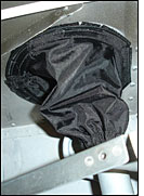
Had a bit of an issue with the brass bushings and control stick bases.  The plans state you have to grind down the parts to get them to fit.  Took a bit of time to get them to size and clean up the parts before I could get them to fit.  Drilling and attaching the sticks was fairly straight forward.  After that you just get the spacing correct and hook the rest of the parts together.  I didn't permanently attach the rods that go outside the fuselage.  I'm going to get some Aileron control rod boots which will limit the airflow from the wing roots into and out of the cabin.


To get everything aligned there's quite a bit of measuring and rechecking.  You have to break out the guide you previously made for the empennage as well as make a new guide for the control sticks.  That gets everything all aligned up so in neural position, everything is actually in neutral.


Guide is the thin metal piece above the control rod in this picture
The picture doesn't portray the excitement of having this section done.  Assuming the wings and the tail-parts were attached you could essentially operate the control surfaces.  Without those on you can still move the sticks around and see everything move which is almost as neat.


Thursday, September 8, 2016

Happy Birthday! Fuel System, Rudder Pedals & Brake System

Happy Birthday RV-10 project!

I received my empennage kit exactly a year ago, so happy birthday unnamed airplane! I knew this was a long term project and had tried to envision what it would look like after a year.  When I was building the benches and trying to explain to my neighbors that I was building an actual airplane in the garage.... well it was a somewhat comical conversation and their reaction is probably typical to most non-aviators.

I'm extremely happy with the progress I've made.  I had a self imposed timeline of about 3-5 years but now I'm optimistic and thinking more along the 2-3 year time frame.  I don't stress about the time that it's taking me. As a first time builders there is a lot I don't know.  Self imposed timelines cause you to build when you don't feel like... which is more like a job than having fun.  This is a bit of a shift from when I starting but now I build when I want to build and am fine if there are weeks that I don't touch the project.  Consistent progress is better than rushing through things and inadvertently making mistakes.

Being a detail oriented project manager type by trade I really like to get into the weeds and figure out as much as I can upfront.  Initially I was worrying about what switches I was going to use before I made my first piece.  It's important to think about these things but the project will constantly change throughout the process. I tend to work through one kit at a time thinking about options on that kit and then the next kit as you move through it.  Even with having the structure 90% complete I'm still unsure of certain aspects of the engine, avionics and interior.

All in all I'm having a blast and learning a ton.  The constant learning is what makes a project like this so rewarding. 

Fuel System

Section 37

As with the brake lines Tom at TS Flightlines not only provided me with high quality stainless steel lines but helped answer questions and concerns that I had. Going off his and some other suggestions I decided to put the fuel flow totalizator on the engine (When I get to that part) and used Air Flow Performance (AFP) filter and pump with an Andair Fuel valve.


As a first time builder some of these lines can be a bit confusing on which lines go where.  Had to confirm with Tom that they went where I thought they went, I was right so that's a plus!  Installation was fairly easy, I used some bushings from ACS for both the brake and the fuel lines under the seat.  Had to remove some material from the brackets just to ensure a snug, but not too snug fit.  Also hope I'm tightening the NTP fittings correctly, hand tighten and go about an extra half turn.


From under the seat the lines connect to the fuel valve.  I went with the Andair because of the higher quality and that I will end up using an extension pieces for the arm rest that will eventually be in place. The factory bracket doesn't fit which requires you to make your own.  Using the original as a template it's fairly quick work.


The lines then run to the Filter & Pump assembly.  The plans call for these to be offset a bit but they can be connected reducing a few possible leak points.  UPDATE: Removing this once installed through the access panel is very difficult.  At first fuel filter check I ended up putting the AN line between the pump and the filter.  This allows me to loosen the end nuts and a single clamp to remove the filter entirely.


Using the factory mount it secures down enough not to shake too much.  Nothing magical but it all aligns well with the mounting brackets installed with the QB.  The rest of it is just attaching the rest of the lines.


That's it for the fuel system until you mount the wings and install the interior.


Rudder Pedals & Brake System

Section 38
Since I was going with the factory standard pedal set up I to actually back order these since I removed them from my original kit.  Lesson learned is don't try and anticipate when an after market product will be available. Go with what's available at the time.  This would of saved me a few hundred dollars because Vans punishes you on back-orders by not giving you the original Kit pricing. 

Putting the pedals together is straight forward.  There is a choice you have to make on which side you want the shop head of the rivets on.  Overthinking a bit about traction I decided to put the shop head on the part where your foot is and the 470 manufacture side on the back.  It apparently doesn't matter and some people actually use flush head 426s and countersinks the pedals. I also decided to leave them unpainted, thought about getting them powder coated but I would guess no matter what you do these are going to get beat up from flying so just left them be.


I finally bought a drill press because this section involves drilling very straight holes.  In the past I did it with a level and my eyes to some goo success, however going a few inches concerned me a bit more.  So with the drill press I was able to make the required brackets and get the pedals mounted in the plane.


 One aftermarket item I picked up were some rudder cover kits.  You can shape them any which way you want, some leave them square, I've seen others shaped as ovals and I decided to just round the edges a bit.  Then used my drill press to make the holes.  Attached them via pull rivets to not risk damaging anything with the bucking bar on the back in.  Gives it a more clean look.  Am debating on installing a set up front, that's going to be covered with interior so might not be worth the hassle, can decide later.


The last part I needed to finish was the Airward RV-10 parking brake. I've seen some people make their own brackets or mount it in a different area, I decided to get the entire kit and mount it as suggested.  I sent the below picture to Dave at Airward to make sure I had it installed correctly prior to riveting it to the firewall and finalizing up the lines.


Above is the completed rudder and brake setup.  Now I haven't finished the brackets to connect the rudder lines to the pedals.  I am going to wait until final rigging to work through that to make sure the rudder is straight with the pedals even.

Monday, August 22, 2016

Firewall/Tunnel and Brake Lines

Firewall

Per the plans the RV-10 uses a single layer stainless steel firewall with aluminium fittings.  This has been shown to melt fairly quick in the event of an engine fire and once your fittings melt then all that smoke ends up in the cabin.  For you non-pilots that's a very bad thing....

Solutions have been discussed over on the VAF forum and Dan Horton has not only come up with a great solution but has provided pictures and test results to back his findings.  The idea is that doing a little more to the firewall will slow any fire as well as help keep heat out of the cabin during normal flight.

His suggestion is what I went with was to cover the engine side of the firewall with 1/8th inch Fiberfrax and then cover that with some stainless steel foil.  Lastly replace all the fittings with stainless steel versions, secure with stainless steel rivets and caulk seams and edges with 3M Fire Barrier 2000+.  Here are his pictures.

General concept
Since the SS Foil comes in 24inch wide rolls this is how you deal with the center seem.
 This was a lot easier than I anticipated, it's a bit of a struggle to work with the Foil but I was able to get it somewhat decent looking.  The worst part by far is the ugliness of my caulking but going for more functionality on this one. I should also note that I used a thin layer of the 3M caulking as an adhesive, relying mostly on the fittings and the caulking to hold it down.  If it starts pulling at a later day I can add some SS Rivets fairly easily.

Bare SS Firewall
Layer of Fiberfrax with 3M 2000+ applied.
I would say I'm 95% complete with the firewall.  I'm waiting on a back-ordered grommet and some nutplates to finish up the control cable area and to attach the oil cooler.  When I get my engine mount I will mark the locations and actually remove the Fiberfrax and Foil from the attachment points.  This will allow me to attach the mount directly to the original firewall as designed.  I will then apply additional 3M 2000+ around these points as well as any additional fittings I might attach later.

I also decided against putting any type of foam insulation on the cabin side of the firewall.  May sound a bit strange since I'm putting a lot of insulation in the plane, but this has less to do with sound reduction and more to keep the heat/cold in, especially since I'm putting an Air Conditioning in the plane.  I'm also banking that the Fiber/Foil bit helps keep the heat out so my feat don't burn up while flying... and I feel keeping foam away from the firewall will help keep my feet from literally burning in the case of an actual fire, or from passing out to the smoke that I witnessed when I putting a blowtorch to the material.

Mostly finished.

Tunnel

(Update: When I started working through Section 39 and installing the control rods it became obvious I was having clearance issues with my below packets installed.  Concerned about having the controls hang up I decided to scratch what I described below and leave the entire tunnel area bare.  If later down the road I begin to have 'Hot Tunnel' issues I will go back through and figure something out.  My hope is between the firewall side heat shielding, using stainless steel attachments and the new outward facing exhaust that I won't encounter any issues.  Only time will tell...)

In earlier kits there was a problem with the center area of the plane, or what's called the tunnel getting extremely hot.  This actually lead to Vans putting out a Service Bulletin. Their solution talks about adding insulation or redirecting some airflow.

For my build my additional firewall work, sealing around the fittings and using all SS attachments 'should' help keep tunnel heat to a minimum.   I've decided against putting anything that will burn or give off toxic gas, for the same reason I'm not putting foam against the FW. I've also heard that the exhaust system for the RV-10 has changed to direct heat out sideways now versus down the middle of the plane.  In the event that this becomes a problem once I start flying then I will work to solve it then.

Aft of the spar in the tunnel I went ahead and used a method of insulation that I'm comfortable with.  It's a bit of a hybrid with what people have used and wasn't all that difficult.  I essentially encased a layer of Fiberfrax and Foam in a Stainless Steel Foil pouch.  This is the same technique I use to smoke ribs and they turn out fantastic, so why wouldn't that work on an airplane?..

Starts like this....
Ends like this, delicious!!!
Installed in rear tunnel

Brake Lines

Section 36

A fairly common deviation from the plans is to not use the 1/4 aluminium tubing for your brake and fuel lines.  There are some better options out there and I went with TS Flightlines for mine. Tom was fantastic helping me work through my order, answered question and was extremely fast to ship out the product.  On top of that the lines look great!  I was able to knock out the initial part of the install in an evening.  The rest of the lines get connected when installing the pedals.

Anytime you deviate from the plans you'll probably encounter an issue here or there.  My issue was more with the hole in the gear weldment that the NTP brake line fitting exits was a bit too big and I didn't like the way it sat in there.


My solution was essentially make a washer out of some scrap and wedge that inbetween the bottom skin and the gear weldment.  I started with using a 1.5 inch hole saw bit and cut out a couple of blanks.  I cleaned the edges of these and used a unibit to put a larger hole in the middle.  Because of how the fuselage side skin connects I needed to shave a bit off the 'washer'.

"washer"
Final Fit
Feels much more secure
 The rest of the task involves running the lines, connecting them to the various NTP fittings and cushion clamps.

Under front seats

Tunnel
Cabin side firewall
This section was extremely quick, I'm guessing not as quick if you have to bend your own lines, flare your connections ect.  The rest of the Brake lines (as well as the parking brake) will be installed when I do the pedals.

Friday, August 12, 2016

Aileron Actuation

Section 23

I had started this section awhile back but unfortunately messed up on some drilling and ended up with my torque tube lengths being too short.  I could of used washers to make up the length but instead decided to try my hand at some welding at a later date to see if I could fill in the holes. Later came and well, instead of welding the holes I basically blow torched larger holes.  I ended up using the piece to practice a few things and decided I'm not ready to weld airplane parts.  Instead I ordered a new tube which was $20 so not an expensive mistake.

Big Gap
With the new part I was able to catch up pretty fast and get the assemblies installed.  The most difficult part is making sure everything is lined up in the neutral position.  If you mess up here you really might not notice until you're ready to fly, which in that case I'm hoping to get some extra help with the rigging so the plane doesn't fly sideways.

New parts properly clocked
 With aligning both the push rods and the ailerons Vans provides you a jig of sorts to help with finding neutral alignment.  This little aluminium piece jig bolts onto the bell crank allowing you to find the correct position for both push rods. This allows you to adjust the pushrods as needed so they're the correct length when you have both the torque tubes and the bell crank in neutral position.  I should mention that I used a ruler and a clamp to find the neutral positions of the torque tubes. Didn't take a picture but in short you want to make sure you put these in the correct position.

Push rod installed

All in all works out pretty well and I'm assuming during Phase I you can tweak these for 'heavy wings' or other unwanted things.

At this point you install your flaps 'temporarily' to find the correct alignment of the ailerons.  I saw temporarily because the plans do, not sure when you take them back off but I guess I'll find out later.  I had problems finding a particular bushing which required me to do some internet searching.  What I came up with was that they were the 6 bronze bushings provided and labeled differently than the plans.
Flap Bushings
It's a very tight squeeze and read that some people just sanded out the area a bit until they could fit them.  Not liking that approach I instead stuck all 6 bushings in the freezer for about 20 mins to shrink them just enough that I could use a C-clamp to squeeze them on.  Worked out well and then to get about the same 1/32" clearance on both sides I used a large nut so the bushing could squeeze through without smashing it.


I again didn't take pictures of the next part but at this point most builders are used to the method of test fitting control rods, remove, adjust retry.  The key is to match the alignment of the flaps to give a straight edge.  Once you have it you can reinstall everything, torque down the bolts and this section is done.
Doesn't look like much but functioning control services are neat!