Wednesday, April 18, 2018

1000 Hour Milestone! Fuel System & Oil System

1000 Hour Milestone!

Before I get into my progress I wanted to point out a particular build milestone. Out of curiosity, while typing this up I wanted to add up the hours I've spent on this build and low and behold I'm a handful of hours away from 1000 hours build time (Will get there tomorrow).  What does this mean?  Well nothing really only that I've spent 1000 hours bucking rivets, cutting/shaping aluminium, deburring, fiber-glassing and all the other fun exciting things you get to do when you build yourself an RV.  What it doesn't take into account is the countless hours you spend researching and dwelling over every aspect of the build. I won't even speculate on how much time I've spent on those activities.

A rough estimate Vans gives you on an RV-10 build is around 2000 hours.  So that would mean on a standard build I should be about halfway done, however I did a quick build which is estimated to save around 1000 hours.  So why am I not done??? It's pretty obvious to me that I have greatly increased my building time (and costs) through a number of modifications or plan deviations which exponentially increase the time you spend on particular steps.   Priming alone will add a good 50 hours to your build.  Add an air-conditioner, add another 50 hours.  Want full blown interior? 50 hours...  you get the point.  The current RV-10 I've been flying is essentially plans built with a carbonated engine and steam gauges and is pretty awesome.

My advice is the same advice given to me and that if you want to streamline your build, reduce headaches and unknown costs then just build it per the plans.  If I had done that I would probably be wrapping up by now... however if you want to customize your build, put what you want in it... that's part of the fun of experimental but comprehend the price/time trade-off.  If I had to do it over again knowing what I know now I would probably not do a few things. That said I'm not flying this yet so can't say anything definitive.  Back to the build....

Fuel System

Section FF4
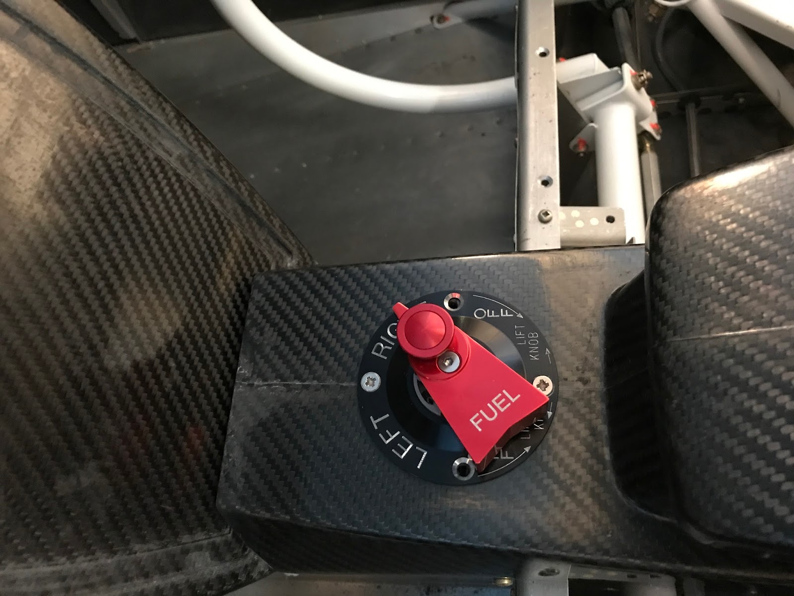
When it comes to these sections I really need to credit Tom with TSFlightlines for helping me out.  He worked with me on figuring out where and how to mount the fuel transducer and custom made my fuel and oil lines to my specific measurements.  Making really the hardest part of these sections doing the measuring of the lines.  If you have a complete stock setup he has those measurements and can just send you the lines, similar to when I ordered my brake and internal fuel lines.

Firewall forward though my system is a bit out of the norm with my forward facing servo.  After taking some time to work through some things, I ended up happy with the routing and obviously the quality of the lines.  Here's some pics

Firewall to Mechanical Pump
Mechanical pump
Line to Servo
Cube right off servo
From Cube/Servo to Distributor

 Oil System

Section FF5
For the oil system I went with the larger Airflow Systems Oil Cooler. Given some of the heat I fly in I wanted the extra cooling.  I am also using a butterfly valve kit from TCW. This allows me to control the airflow and in turn control the oil temp better.  The idea in the summer have it wide open, in the winter time you can close it a bit to ensure your oil heats enough to boil out any water. Water/Oil mix in a sitting engine is bad! These modifications were fairly simple to do. I haven't mounted the servo yet for the butterfly valve but the rest is done!
Oil Cooler and Lines
Overflow and Oil Pressure
Oil Pressure into engine

Engine Plumbing Complete!

Sunday, March 18, 2018

Exhaust System


Section FF6
Jumped from FF2 straight to FF6...  Section 3 - 5 deal with cables and lines which I am getting custom made.  I thought about waiting till all that was done before installing the exhaust system, it would sure make it easier to do this and the FWF wiring if the exhaust wasn't in place... but I don't like the easy route so I decided to make the build even more challenging by mounting the exhaust! 

In reality my decision to go ahead and mount the exhaust was a bit more practical.  I have no idea how I'm going to route the fuel lines, control cables, oil lines, cowl flaps and all the little bits and pieces that will be crammed into the engine compartment.  If I did all these and then installed the exhaust there's a high probability I would have ended up having to redo items that conflicted with the exhaust.  With the exhaust in, I can route around it... a bit more challenging but will ensure no conflicts.

If you take a look at the above graphic you'll see it's actually the directions for an old system they used to have.  They tell you to follow the directions that came with your exhaust and jump to page 5 where they have a bunch of pictures of the finished install.  The plans that came with the exhaust were 3 pages complete with copies of the hand drawn items tell you how everything hooks up.  Some of it was a little challenging from a bolt manipulation perspective, but it all went on fairly smooth.

Interesting mounting bracket system
Left ramp modification showing fit, worked well.
Final install

Saturday, March 17, 2018

Cowl Baffle

Section FF2
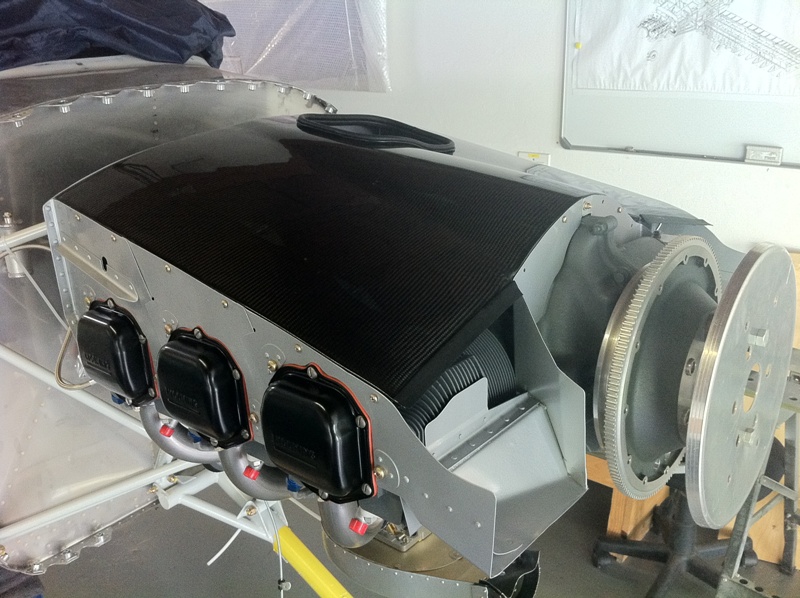
You have two routes you can go in terms of getting cool air to the engine.  One is the use of a plenum while the other is per the plans and essentially uses aluminium dams and a rubber type material to direct the airflow.  I decided to stick with the later in effort to not over complicate things. Initially working through things was fairly straight forward.  Its back to messing with metal and following the directions. Should note that I was doing this section concurrently with the cowl fitting because later in the process you need to start putting the top cowl on to achieve a 3/8 - 1/2 inch gap.  I'll make that it's own section because that has been quite the process.

Once you have the gist of the pieces put together you start test mounting it on the engine.  I went ahead and covered up cylinders 5 and 6 so I wouldn't scratch the valve covers.  There's very little trimming required to get these all on.  Cylinder 6 is tricky but once you figure it out it's a repeatable process to put it on and off. When I got to the pages on the inlet ramps that is where it stopped being straight forward and turned into quite the headache....

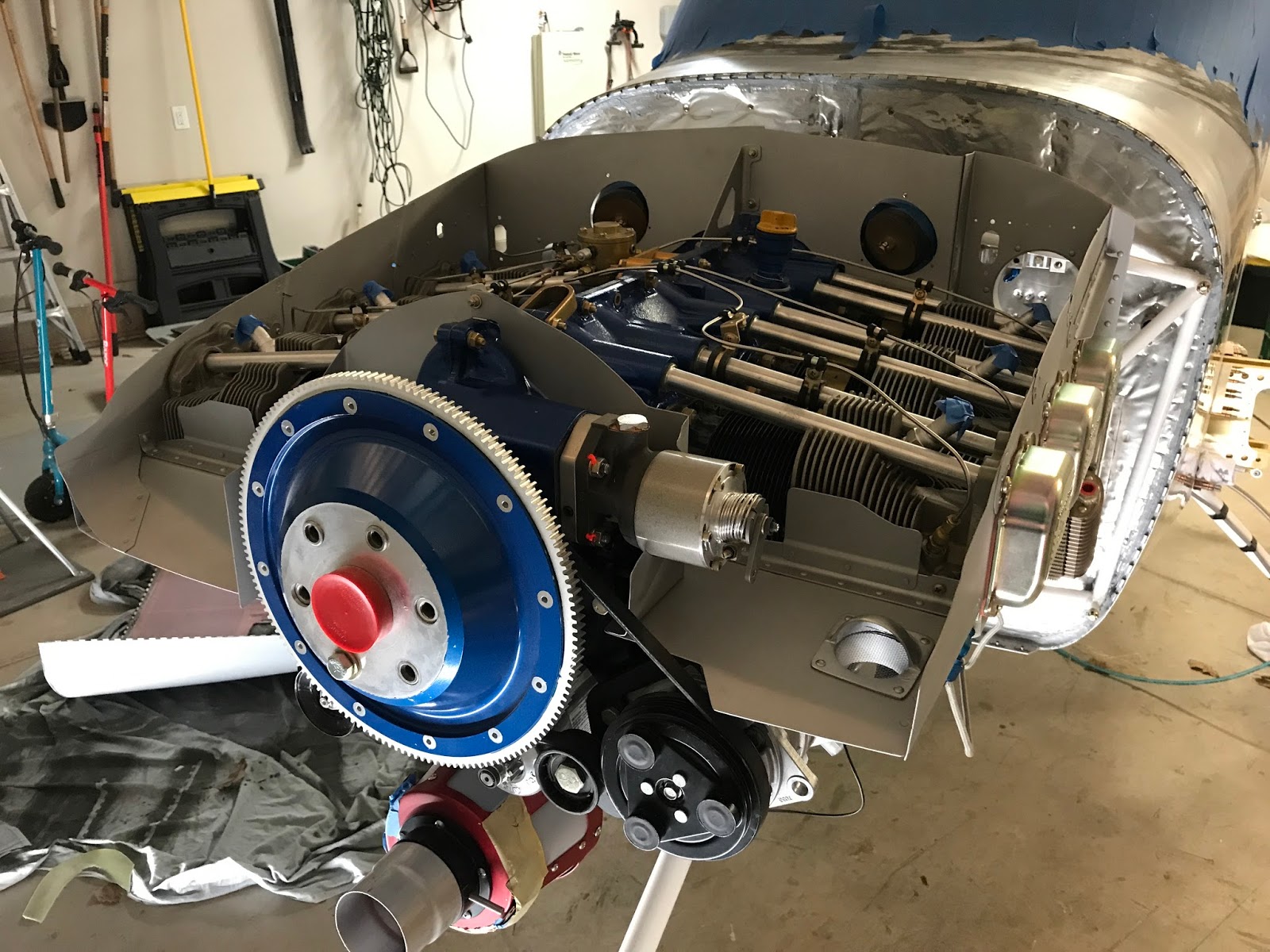
See I'm putting in an Air Conditioning which means I have a compressor located on the port-side of the engine.  This prevents a per the plans install since the inlet ramp can't back downwards.  I actually knew all this going into it so it wasn't a surprise.  Once again I reached out to Greg for some guidance as well as checked out his install. If you look at his pictures he made a fiberglass ramp and keep the inlet ramp moderately flat so I followed suit... hence why I was needing to install the cowl and work the baffles in concurrence.  Before I get into that, here's a nice picture showing the initial fit, when I still had the prop on.


I have a feeling each install is going to be a little different when installing a compressor and there are variances in height and pulley wheel position.  I tried to keep at least an 1/8 inch gap between everything to keep things from rubbing.  Also with the compressor there was a slight challenge getting the front ramp on and off with the governor on.  So I had to loosen the bolts and remove it and then slide it back on to finish out the fitting.  As you can see in the picture (which wasn't the final trim) that a lot of customization was needed.  Especially in the piece around the governor where I used the stock piece but made new flanges and opened up the hole to fit. This is an early picture so it's before I really cleaned things up and made the hole for the exhaust cooler air.


After getting the inlets in place I began trimming the the baffle to get that 3/8 - 1/2 inch gap.  I used the paperclip method for that. You take a lot of material off, a little at a time.  Once the top cowl was able to be reinstalled I focused on a section at a time.  This allowed me to focus on ensuring I wasn't shifting the top and in turn the paperclips in any strange way.  All in all I spent upwards of 4 hours doing this and that was even with some help.

With the final lines drawn I removed everything to make it easier to get a nice smooth consistent line.  After going through and deburring everything in great detail I roughed up to prepare for paint.  Obviously painting in an option but I like the look of a painted baffle, even thought I picked Aluminium as the color.  Also want to make sure you get a paint that can withstand high temperatures, I picked an HVT product from my go-to online paint store RE Paint Supply.


Paint drying
 Once everything dried I was able to get it all put back on the engine.  This includes the governor that I had unbolted to get the custom ramp on and off.  Really like the way it all turned out.


Following the experience of others I went a bit arts and crafts and made paper templates for the baffling material. I wanted to be able to cleco these on so I went ahead and put some 1" thick tape around the perimeter and drilled the holes about 3/8 down and spacing varied depending on the piece but was between 1.5 - 2".  There's one spot over #1 cylinder that there's really not much material so the spacing is more like 3", just had to ensure good RTV coverage later on.

With the holes drilled I started making some templates out of construction paper.  The idea was to have the more forward piece overlapping an inch over the next piece.  Idea being that when air shoots in that it will help force the overlapping down, keeping air from escaping.  With the paper in place I cut the top to have about 2.5 inches of material above the aluminium damns.  This was to account for any variations post install, easier to trim than add.

Not pretty but serves the purpose
Laid out the templates and started cutting the baffle material.  Once cut I went ahead and drilled two of the cleco holes to get it in place and then using a reamer match drilled and cleco the rest.  You need to use Acetone to clean the release residue from the baffle material to ensure good adhesion for later RTV application. Then it's just a matter of using the provided pull rivets and putting everything in place.  After that it was fairly easy to give the material a hair cut to a consistent 2" per Vans suggestion.

Per the plans you have to apply RTV anywhere that air could escape.  My previous work with RTV was out of a little 3 ounce tube which is a pain to work with, especially thinking about trying to run long beads with it.  I picked up a can of this which made easy work of it.

With the major work done I'm calling it good for now.  I need to finish up the tension rods, which I'm replacing the stock stuff with 6-32 all threaded rod which is on order.  Also need to reconnect the spark plugs and need to order the Ignition wire harness seals.  Also anticipate some final trimming as I put the cowling back on, but no reason to go into detail on that stuff.


Saturday, February 10, 2018

Transition Training

I've flown a handful of single piston general aviation planes and each time I spent some time with an instructor doing some transition training. I knew with this project that I would defiantly want to do some type of transition training before launching my project into the air.  There are a few CFIs out there that offer RV-10 training with the closest one to me being Alex in Dallas. I had planned to try and schedule sometime this summer to do this in preparation for my first flight. Luckily for me however a good friend of mine bought back his old RV-10 and offered it up for me to fly!

N188MS
Now my friend isn't the builder, he bought it initially from the original builder who pretty much did a per the plans build.  It has a lot of similarities to what I'm used to flying such as push-pull controls, carbureted engine and a steam panel.  Differences are obviously the performance, constant speed prop and it's a low wing.  Fun fact though is this is the only RV-10 I've ever flown in. I was able to sneak a ride in with a guy flying it for the previous owner.

I started my transition training by sitting in the plane and working through a checklist that I had downloaded.  Being an experimental aircraft, people generally make their own which works great for me because I always make my own checklists.  I'm big on flows and my checklists need to follow that.  I spent a good hour or so revising a checklist and going through the phases of flight, flipping switches and making airplane noises. I took my revised list and worked it up into the format I used on my custom 172 checklist.  The end result I get professionally printed two-sided and laminated in a 6" x 9" format. 

Checklist Format
With a new checklist in hand I was ready to do some flight training.  Britton Lee is a CFI, CFII, MEI, ATP and A&P who flies out of my home field.  She flies all sorts of planes and types so I had full confidence she could square me away on the RV-10.  My first flight was under and hour and we did some PTS maneuvers to include stalls and emergency procedures.  I felt a bit behind the plane, my first checklist revision was a mess, there was also more power than I was used to and the gauges are arranged in a bizarre 1960's Cessna 150 stack vs a traditional 6 pack.  We only did one landing because earlier she flew with my friend and said there was a bit of a nose shimmy.  Upon landing I agreed there was a nose shimmy.

Luckily I have installed an RV-10 nose wheel so decided to take a look.  I had also previously seen this PDF on VAF so I knew it's a common issue. Essentially what I found was greased up washers resulting in almost no resistance on the front wheel.  I took it apart, cleaned and dressed the washers and reassembled with the proper 22 lbs break.  I also found the wheel pants cracked so I fixed that too.  Great news is it was a success.  My buddy flew the next day and said there was about 20% of the shimmy it had before.

My next flight with Britton I wanted to do just pattern work. I was able to do 4 touch and goes, all successful but a bit all over the place.  I was high at times, low at times, left of center, right of center.  Not my best but with only 5 landings in the plane I was comfortable.  Britton said she felt I did great and said I should plan to take the plane up solo.

With a whooping 1.5 hours PIC in the RV-10 I made the decision to go ahead and do one of my go to XC routes from KHSD to KCSM and back.  KCSM is the perfect place because it has a 13,500 ft long, 200 ft wide runway.  You also fly over about 5 airports so if you have an issue you can get down fast if needed.

I wish I could say it was an uneventful flight, but that's not the case.  It was a bit windy at around 15 knots gusting towards 20 but it's straight down the runway and not out of my comfort zone.  Take off was a non-issue and followed my flows/checklist watching CHTs, squaring up the engine and being amazed at how fast I got to 8,500.  Once at 8,500 decided to test out the AP and spent about 10 mins verifying all the functions.  As I approached KCSM I checked the weather and tuned to tower.  The airport traditionally has military heavy's like KC-135s and suck working in the pattern.  I've never seen more than 1 though until this flight.  As I'm approaching there's 1 in the pattern, one on a 5 mile final and 3 lined up ready to take off.  The controllers are always good about working you in so I had to extend my downwind a bit and was sequenced between the two giant airplanes.  Wake turbulence is always a concern so I watch to see where the one in front of me landed so I can land in the spot he did... well he ends up just doing a low approach or maybe a touch a go... either way he was down and up really fast.  I make the decision to carry out and land midfield to avoid the possibility of getting caught in some nasty vortexes.

Landing was good so I cleaned the plane up and took right back off. Thanked the controllers and shot back up to 7,500.  Set the AP and knowing I had a bit of a tailwind checked my ground speed once I was straight and level... 196 knots!!! For you non-pilots that's 225 mph and about twice as fast as my 172. Being impressed I decided to snap a picture (bottom left shows the speed).


After a few minutes seeing just how fast I could get the plane going I decided to reduce power to a more efficient 70% or so setting. My typical flow is pitch-power-trim-mixture-instruments... this repeats itself over and over again in my head when flying.  When I got to instruments I noticed something concerning.  The ammeter was showing a power draw, vs a healthy charging system that shows either a charge or 0 sum.  I double check to make sure the lights and fuel pump were off, I then turned off the AP thinking maybe a servo was malfunctioning.  I check the alternator pull-breaker and then go ahead and pull the breaker with no change to the ammeter.  I then try to reset the alternator switch... nothing, I'm all battery now baby!

Some might deem this as an emergency.  Unfortunately this is literally the forth time I've had charging issues while flying... once actually on this same route.  It's all old hat to me, so I decrease the load on the battery by turning off the avionics switch.  The idea is to conserve enough power for radio and flaps when landing.  Pretty much a straight shot but it's a bit hazy so I break out my phone again and pull up my EFB to get weather and make sure I'm heading the right direction.

About 10 miles from the airport going about 180 descending, I power everything up.  Make my radio calls and enter base with about 20 degrees flaps.  Some will argue that you shouldn't go full flaps if you have to do a go around and you can't get your flaps back up.  I somewhat agree and wait till I have final made before dropping full flaps.  I landed a bit hot at around 70 knots... still off by mid field.

So there you have it, an exciting first solo in an RV-10.  They are really great airplanes and I look forward to putting some more hours on my buddy's plane while I finish mine up. As to not be complacent I also plan on working more with Britton. UPDATE: Tragically Britton passed away in an accident.  She was well respected and will be missed.

First Solo Landing... Pre-power issue...


Tuesday, January 23, 2018

Engine Installation

Section FF1

The Firewall Forward RV-10 plans consist of six subsections that you follow if you're building a 'per the plans' plane.  My build deviates from the plans with using different control cables, oil cooler, AC, Ram Air ect.  These deviations require you to do your own research, see what others have done and engineer through it.  By the time you get to these sections you're well into your build and familiar with figuring things out.

Mounting the engine involves acquiring the actual engine, which I ordered late last spring and even though it took longer than expected but it was worth the wait.  Last week I was able to do the short drive to Tulsa and pick up the engine from BPE.  I borrowed one of my buddy's trucks to make the journey and it was an easy drive, an easy loading and easy transaction.  I can't say enough about Rhonda and Allen and the assistance they gave in working through the process.

Engine loaded up
The actual process to get the engine from the truck to my garage was a bit more lengthy.  It's a big box, is over 400 lbs and not something I want to just toss around.  I decided to play it safe and we moved it from the pickup to another one of my buddy's trucks... (A rollback). May have been overkill but in the end it arrived at my house, we man handled it into the garage and unboxed it to get my first look!

Lycoming IO-540-X
Knowing hanging the engine isn't a one person job I recruited the 'Dream Team' of motor mounters to come help this weekend.  It only took about an hour to hang the engine. The first three bolts were relatively simple but the last one was a fighter.  I don't know if it was the engine or the mount but we had to wrestle a bit to get it lined up. After that it was torqued up, cotter pined and done!

Group action shot
So many hands
So the engine is now mounted on the plane.  It's much harder to push around than it used to be and she'll stand on her own without the tail being supported.  From this point there are essentially three things I can work on independently of each other.  There's the engine work which involves hanging the accessories such as the alternators, AC compressor, Ram Air, ect.  There's the next FWF section with working on the brackets.  Then there's going back to the Finishing section on installing the prop and cowling.  These items should keep me busy into the Spring!
Some additional pictures that some might find useful.

Front

AC Compressor

AC Compressor and Prop Governor
Primary Alternator

Secondary Alt

Elbow and Fuel Servo


Friday, December 29, 2017

Holiday Panel and Electrical Design

Panel

It has been close to a year since I originally posted my plans for a panel, electrical system and component location.  With 2018 around the corner I wanted to get the new year's designs out before the end of the holiday season.  So without further adieu, I present the N10JW 2018 Panel!

I have been working with Stein Air the last few weeks on this design and we went through 7 revisions to get to this.  Very easy to work with, might have helped that I had a mock up put together to start with.  Should note the labeling isn't accurate to what will be on the panel.  I'll continue to work with them on the atheistic parts, this picture is all about functionality.  Here are some of the substantial changes from my old design-

  • Replaced my overly complicated Mag switch / start sequence with a tried and true ACS style key switch. While I liked the idea of holding two toggles up to start, it's a bit too complicated and not as easy as turning a key.  Push button would also have been neat, but then there's still a mag sequence to start..  in the end ease of use won.
  • Incorporated both the CO2 Test and warning light as well as a low voltage light and battery fault (EarthX Battery).  My original idea was to see these errors on the PFD, but if there's a battery issue and it's not powering on then I can see the fault light.
  • Removed Autopilot Power switch because I determined it's not needed.  If I can't turn the servos off via the autopilot panel at the top, or withing the G3X or manually through the VPX then I can always just turn off the avionics (PFD stays on).
  • My light control switches wouldn't fit in the middle section of the panel so I moved them down to the lower console.  That allows me to move the dimmers to the middle panel area which in turn allows me to spread the radio stack out a bit.
  • Added a 'Spare' to the left of the AC power and fan control.  Right now I'm thinking I might wire this up to disconnect the Co-Pilot stick buttons. Default would be just to have it off unless someone is flying from the right seat.
  • Added two traditional Circuit Breakers for the Air Conditioning. The AC pulls a lot of amps and no reason to route it through the VPX.  Instead I'll use traditional push-pull CBs for the power.
  • The only other real change involves the mapping of the control stick buttons.  I wasn't sure what I wanted to use for button 5 on the Infinity sticks until I cam across this... which helped me make my decision.


Electrical Design

Periodically over the last year I would get into my Visio file and do updates to my previous baseline.  Most the time it was the panel, but lately as I started to hone down on some decisions it's been to the other more important sections, ie component layout and power distribution.

I finalized on going with a dual alternator and essentially a limited dual battery system.   I call it limited because in case of battery, contactor or a VPX failure, my backup battery will only power up the PFD, engine and direction components and the GTN 650 GPS and comm system.  Now if this all takes a dive then I have a G5 to help keep my wings level.  All this really only matters if I'm in the clouds and can't see the sky or the ground.  This set up should give me a few hours to get out of the weather and on the ground.  The balance of simplicity with redundancy is something I focused on and am happy with my design.

I'm in what I would call the 'white gloves' phase of my design planning.  The major stuff was in there just needed to QA it a bit more and be methodical about it.  The first part was to get into my component drawing and remove or adjust anything that I know I don't plan on installing. The only major component I took out was the secondary ADAHRS (GSU 25).  I learned the G5 can and will perform this function, sending info to the G3Xs if the primary ADAHRS goes down. This is a simple enough drawing that it's easy to change on the fly and adjust as needed.
Component Layout
Next I jumped into my VPX Planner and ensured I have accurate Max AMP draws and circuit breaker values.  I say Max AMP draws because you want the circuit breaker to be able to support it, even though your typical pull may be different.  Strobes are a good example of this, they obviously draw power in bursts vs a constant drain. This is important when sizing your alternator.

After I worked through the two above items I got to the meat of the work and that is updating the power distribution drawing.

Update - When I posted this originally a few days ago it was based on the assumption that each landing light would only need a 5.0A breaker.  After talking with Jesse over at Saint Aviation he suggested I keep them at 10.0A each.  I highly respect Jesse's knowledge and expertise on the subject of RV's so I had to do some modifications. That's really how fast these things can change, I fully expect this to continue to change until the plane is up and going.


RV-10 Electrical
A lot is going on in the above drawing, but if you know a bit about what you're looking at it starts to make sense fairly quick.  The idea is that if someone who didn't build the plane needs to know how things are connected they can view this schematic and get up to speed. As the builder, even though I haven't ran a single strand of wire yet, I have a path and plan to how from a power perspective things are connected. You're limited to 32 power pins off the VPX so most will supplement with a fuse block of some sort in order to provide power to non-critical flight items.

Tuesday, December 19, 2017

Pushing On & Partial Move

Pushing on!

Congratulations to me on becoming a Hyatt Globalist this year! Unfortunately that means I've been on a lot of work travel over the last few years, which adversely affects the time I've had to work on the project.  Sad to say it's been 3-months since I completed a major evolution, however when I'm in town I try to continue pushing forward, racking up some hours and getting closer to the proverbial finish line.  Most everything in terms of time is going in the 'finishing' section because I made the assumption that interior, avionics, AC and such are 'finishing' type items.

As I await the engine to be assembled, tested and crated for me to pickup (Hopefully this week) I've been working through some other tasks over the last few months-

  • Panel Revisions - Last January I had a panel design that I really liked.  In the end though I decided to try and simplify it as much as possible and am currently working with SteinAir on finalizing the layout.  The equipment has stayed the same for the most part but I removed my overly complicated Mag switch and starting sequence and decided to go with the standard ACS style key and starter.  I also removed the AP Power switch given that there are several ways already to turn off the AP if there are issues.  Lastly where I thought I was going to have the light switches, in the end they won't fit so those will move down.  Still in the process but looks more like this now-


  • Electrical Drawing - Also last January based on my anticipated equipment and configuration I put together a very detailed power distribution drawing along with a Visio book containing all sorts of other documentation. Have been working on this, I've gone back and forth between some ideas but again to try and simplify things as much as possible with still providing a good level of redundancy, I've made changes.  I'm still thinking dual battery (One being an IBBS), dual alternator and if all else fails the Garmin G5 with it's own backup battery.  The G5 also acts as a backup ADAHRS.  Between all these, if I'm in IFR and things start going south I should have enough redundancy to get me out of the clouds and someplace safe to land.
  • Interior Panels - I started receiving my order from Aerosport a number of weeks ago. I have some experience working with plane plastics so I'm somewhat comfortable working with them.  My process is get everything fit and installed.  Then I'll go back through and remove everything, refinish it and when able reinstall the parts.  Some parts such as the rear panels can really go back in immediately, where the forward kick panels can't be installed again until after Avionics and wiring is all finished up. Here are a few pictures of the fitting process-


Partial Move

My 3-car Aeroplane factory is getting a bit crowded again.  With the engine coming I decided to go ahead and move the wings and the horizontal stab to the Hangar. This frees up the shelving above my garage to store some parts and clears out a bit space where the 15' long wings resided. Several things had to happen for me to do this.
First off my hangar was a bit of a mess.  On one side there was all sorts of odds and ends from our 172 restoration project. On the other side there was a grave yard of old broken ripped out parts from an A&P we once used.  I've tried for years to get him to get the stuff and decided to finally just trash it. I also wanted to move one of my long workbenches, a tool chest and some other things to start prepping an area to final assembly the project.  After about 6 hours I had cleaned it up, celebrated with an hour long flight in the 172 and then snapped a picture before putting the plane back.


Moving the wings was a bit more of an ordeal.  I rented a 17' box truck with the intent in rolling the wings up the ramp and strapping them down.  A friend of mine came over to help and I'm glad he did.  The ramp was about 1/2" too narrow... or I guess maybe I mounted the wheels a 1/2" too wide.  Either way, him and I had to lift the wings and cradle into the back of the box truck.  Once strapped down there was about 1" clearance between the end of the cradle and the door.  Happy to say the wings made the 20 mile trip with no issues and they now live at the Airport.