
 |
| Section 47 |
Spinner
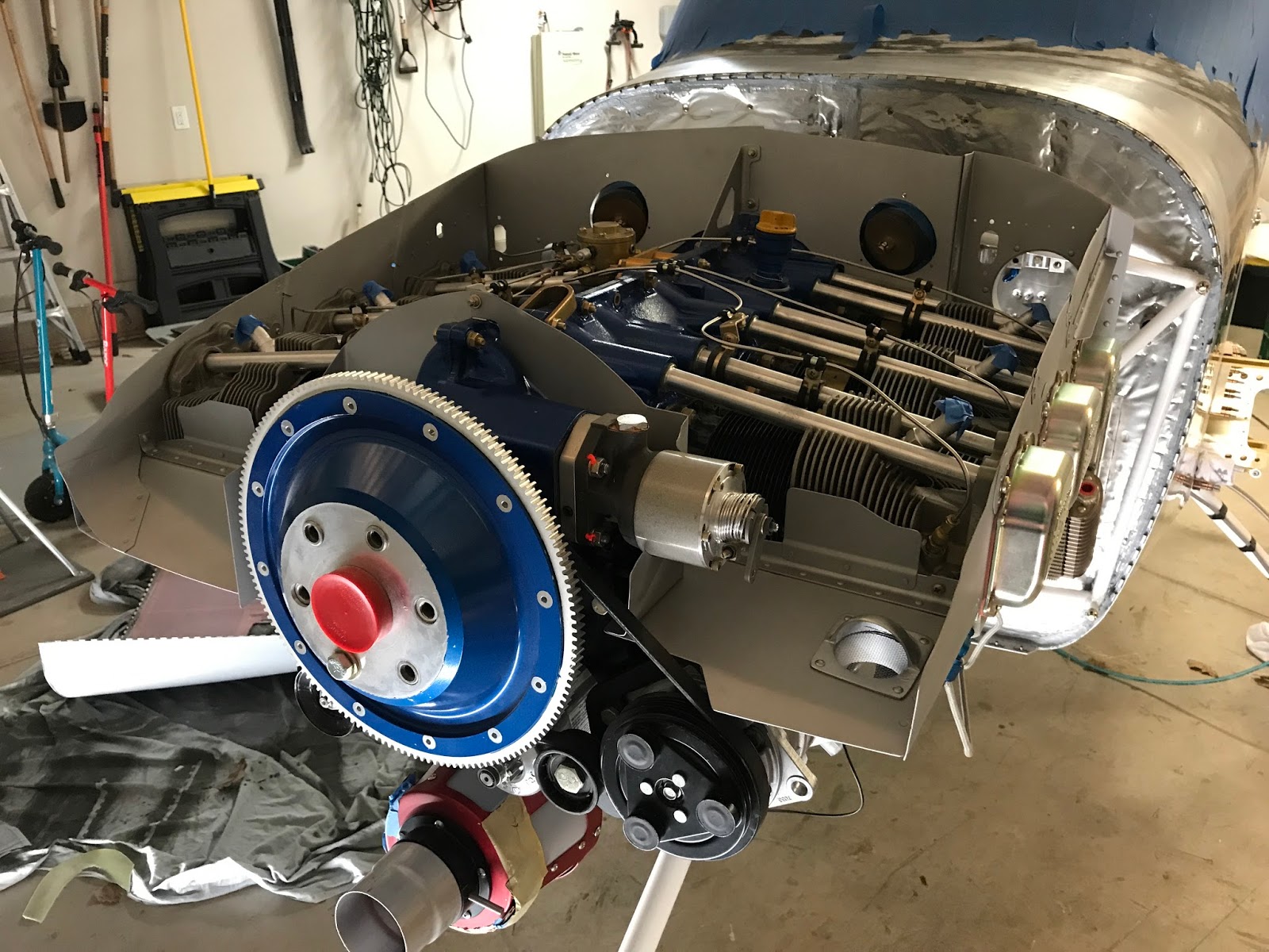
Mounting of the actual propeller is one of those times when you just stand back and marvel at the awesomeness. Making it even more awesome, as shown in the picture I went with the gorgeous 3-blade Hartzell composite propeller. This decision wasn't really grounded in actual performance gains but more or less for up cosmetic ramp appeal. It just makes the plane look fast, even if it's not moving. There are some benefits supposedly with going this route. It's a lighter propeller and it may be smoother, it's reduced diameter has an added benefit in mitigating prop strikes. In reality though I'm sure I'm just looking to justify the added expense...The stock spinner you receive is a fiberglass cone which takes some modification to work with your installation. I am unable to use that with a 3-blade and instead I bought the Hartzell shiny polished spinner to use. Because I had no part fabrication this section was fairly straight forward and even though mounting the prop was a bit cumbersome, I was able to do it solo without many issues.


Now the above picture was taken awhile ago, prior to initial fit of the cowl. You need the prop, or some sort of back-plate installed to get the proper spacing between the cowling and prop bulkhead. The goal for this is 1/8th of an inch which is pretty tight. I didn't trust my template making skills so instead just decided to use the real deal.
Removal and installation the propeller doesn't take all that long, but is a bit awkward. I've found using some of my custom made floor jacks help to act as a shelf to get the alignment down. Then it's a matter of tightening 6 bolts in the typical cross pattern fashion until everything is secure. Torque it up to 25 ft lbs or 300 in lbs (For my Propeller) and call it good. For my first install I used a typical open ended wrench which was a bit of a pain and I had no method to torque it down. The torque wrench called out in the Hartzell manual is a good $600. If you can borrow one great, if not do yourself a favor and buy the Ultimate Propeller Wrench. Not only does it speed up the nut turning but then you flip it over and you can attach a torque wrench in the typical 90 degree fashion for your final torques!
Cowling
Out of all the sections I've worked so far I found this by far the most annoying and frustrating... a close second is still the doors. I take responsibility for the frustration though, it is entirely my fault for the add complication and time. Having added Pin covers, Air Conditioning, Ramair, oil door, cowl flaps and the such really are all self induced, per the plans might be less frustrating but I won't know on this build. The rest of it is just the nature of fiberglass which still is a bit of a challenge for me.
Followed the plans for the most part in getting things clammed together, doing some sanding, trimming and more sanding. You'll notice the cut out for AC Compressor clearance and a big cutout to get around the Ramair unit.

I find when I'm working through a task and getting pissed or otherwise frustrated that I don't seem to take pictures. Here's a quick run down of the work. There's was a lot of sanding to get the two halves together. The idea is to get them even with the smallest gap possible. I used rulers, lasers, tape... anything to try and ensure it's symmetrical and even. I obsessed a bit about this and spent at least 3 work sessions on doing all this... good news is it's fiberglass so if you mess up you can easily repair.

The next hurdle came with putting the clams together and cutting the back off so they are a good 1/8 back from prop and even wit the fuselage. The plans call for measuring a line 3" back, placing the cowling on and then measuring a line 3" forward. I botched this up a bit and end up cutting off too much in some places. I thought about using the laser for this and in hind sight that's what I should of done. My concern though was as it bends over the top and bottom that it wouldn't line up. Either way it was fit on and then attached the other half of piano hinges. Fairly straight forward, had to do some spot sanding in some areas.
Once the backs were attached then I had to work the sidelines. To be honest I'm not 100% sure how I did this. I'm pretty sure I just made a line with a ruler and started trimming. Then attached the piano hinges and all that and squeezed everything together. Spacing is always a concern so I reached out to a 3 time builder to ask advice on what he did. He suggested using a Perma-grit F102 to work the consistent spacing. This worked out fantastic and even though it seems a little wide, I know paint will fill it but it's still not too tight that it will crack the paint.
With the sides being near perfect I was left with dealing with the back of the cowl. Some of the repair was easy just micro/epoxy fill. Some required me doing a scarf joint and using cloth. It was a back and forth deal of adding, sanding, testing strength, fixing etc.


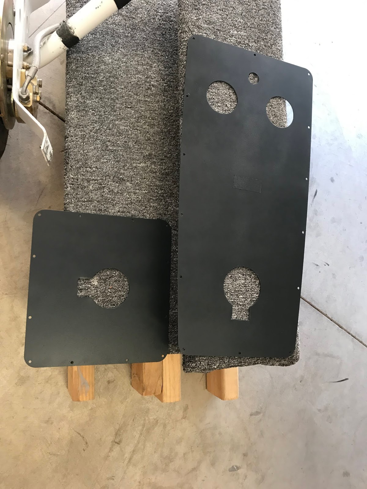
This finishing touched on the oil door was another process in itself. I bought and installed these push camlocs for the opening and closing mechanism. They initially worked well cleco'd on but once I painted the pack of it started the micro fill work I wasn't happy with it at all. I ended up stripping the paint from the backside of the door, adding some shims to hold the latch mechanisms providing better clearance and then I was able to reinforce their attach points with a few strips of aluminum. I bought some 5/8 hole covers also and used some 3M adhesive to act as the button extenders. The rest was a matter of filling in some of the gaps to make it a smooth run, sand, epoxy, sand and here's what I ended up with.


Followed the plans for the most part in getting things clammed together, doing some sanding, trimming and more sanding. You'll notice the cut out for AC Compressor clearance and a big cutout to get around the Ramair unit.

I find when I'm working through a task and getting pissed or otherwise frustrated that I don't seem to take pictures. Here's a quick run down of the work. There's was a lot of sanding to get the two halves together. The idea is to get them even with the smallest gap possible. I used rulers, lasers, tape... anything to try and ensure it's symmetrical and even. I obsessed a bit about this and spent at least 3 work sessions on doing all this... good news is it's fiberglass so if you mess up you can easily repair.

The next hurdle came with putting the clams together and cutting the back off so they are a good 1/8 back from prop and even wit the fuselage. The plans call for measuring a line 3" back, placing the cowling on and then measuring a line 3" forward. I botched this up a bit and end up cutting off too much in some places. I thought about using the laser for this and in hind sight that's what I should of done. My concern though was as it bends over the top and bottom that it wouldn't line up. Either way it was fit on and then attached the other half of piano hinges. Fairly straight forward, had to do some spot sanding in some areas.
Once the backs were attached then I had to work the sidelines. To be honest I'm not 100% sure how I did this. I'm pretty sure I just made a line with a ruler and started trimming. Then attached the piano hinges and all that and squeezed everything together. Spacing is always a concern so I reached out to a 3 time builder to ask advice on what he did. He suggested using a Perma-grit F102 to work the consistent spacing. This worked out fantastic and even though it seems a little wide, I know paint will fill it but it's still not too tight that it will crack the paint.
With the sides being near perfect I was left with dealing with the back of the cowl. Some of the repair was easy just micro/epoxy fill. Some required me doing a scarf joint and using cloth. It was a back and forth deal of adding, sanding, testing strength, fixing etc.


 |
| Attached |
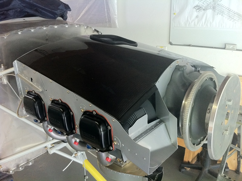
The above picture wasn't the finished product, but it was on enough that I could continue work on the baffles as well as start finishing, working the Ramair etc.
Oil Door
I'm not overly impressed with the plans oil door. It seems flimsy, you have to manually hold it up, the fasteners don't look streamlined... I followed other builders and decided to change it up. I bent up some aluminium to match the door profile and using some adhesives secured those together. Then I bought a hidden door hinge and some different fasteners and put it all together. Took some micro filling and sanding to get it all smoothed out but I like how it turned out in the end.


This finishing touched on the oil door was another process in itself. I bought and installed these push camlocs for the opening and closing mechanism. They initially worked well cleco'd on but once I painted the pack of it started the micro fill work I wasn't happy with it at all. I ended up stripping the paint from the backside of the door, adding some shims to hold the latch mechanisms providing better clearance and then I was able to reinforce their attach points with a few strips of aluminum. I bought some 5/8 hole covers also and used some 3M adhesive to act as the button extenders. The rest was a matter of filling in some of the gaps to make it a smooth run, sand, epoxy, sand and here's what I ended up with.
 |


RamAir
Lets talk a bit about Rod Bower Aviation products. My reasoning in going with these products was ultimately to enhanced performance at a cheaper cost point than a typical cold air induction setup. There are some utility benefits as well. These include easier removal of the cowling with a 3-blade propeller and a built in alternate air source. I can't speak about the results because I'm not flying yet but two people I've spoken with are very happy with their results and have easily achieved an extra 1" on manifold at altitude.
If you're going down this path on an RV-10 you need to make sure you're getting all the right pieces. Even though I ordered mine less than a year ago there have been some changes to unit. I was able to send my unit back in for a nominal labor fee and have it retrofitted to the newer Enhanced Filter Air canister. The difference in the two units are rectangle vs oval reeds, with the rectangles apparently being more efficient than even the stock set up. Next I picked up the Rambo Elbow which re-positions your servo horizontal and forward facing giving it a straight shot of air vs the typical updraft model. No clue how that affects performance but we'll see.
To be completely honest the biggest challenge I had was with the fiberglass scoop. The original one sent to me fit the cowling great if the canister was in the original position. With the elbow and forward facing fuel servo it moves it up and out and the stock location wasn't going to work. It was obvious to me that it wasn't going to fit initially. I thought maybe when you used the elbow you had to do some fiberglass work, sent some pictures and emails to Rod and got some advice on how to make it work. In his defense he's not standing in my garage so it's probably a bit challenging to understand what the issue is. We had a number of conversations and I was ready to bastardize the scoop I had to get it to work. Rod gave me some suggestions on cutting the flanges off, how to position it etc. Even after doing that there was no possible way this was going to work. At this point I'm reading through making molds and all sorts of stuff and came across Larry's thread on his install.
A couple things I noticed, 1) he has the old oval reed openings, 2) he had to machine his elbow to put a 3 degree angle in it and now Rod sells spacer for that, 3) His cowl scoop looks amazing! So I reached out to him to see what sort of techniques he used to get such a great fit and he said he had to do very little..... Okay at this point I knew without a doubt I had the wrong scoop so I sent Rod some of the pictures and essentially said 'I need what Larry used'.
I hate that I ruined the original scoop so couldn't send it back, but I was more than willing to buy the new scoop which I did. A few weeks later I had the new scoop, which essentially fits perfectly. All I did was even out the flanges a bit but other than that I didn't have to do any major fitting. All in all in the scoop I'm guessing I spent less than 3 hours fitting it, cutting the matching hole and working the micro and fiberglass work. I spent another hour or so installing the camlocks and now I also have an amazing scoop!

Cowl Flaps
Lets talk Cylinder Head Temps (CHT). In the RV-10 I'm flying now you have to shallow your climb pretty soon after lift off to keep the CHTs under 400 degrees. This threshold is optimal as you don't want to burn them out or be overly hard on your engine. There are troves of information out there on a variety of topics to reduce the CHTs. There are a number of builder who do pretty much everything possible and still end up not being able to climb at their maximum rate, and those in hot climates such as mine that really have to reduce their performance to keep CHTs down. The solution for me are using Cowl Flaps in order to increase airflow on climb out. Cowlflaps aren't a new idea and have been around at least since at least WWII. I've flown planes with them and I don't find their use overly complex so wanted to incorporate them.
This is obviously a deviation in the planes and require some modifications. They go in place of the stock vents and you'll want to make sure that at no time are they interfering with the exhaust. Two major issues come up when you plan the install. The first issue if the only place to avoid interference is at the inner most corner all the way back. This causes you to have to figure out a method of attaching the center brace piece along with the flaps.
The second the flaps will be proud of the cowl, sticking out a good 1/8in inch of you don't build up the material behind it. Other builders have come up with methods of building up the area. I tried to make a metal bracket but was having some consistency issues with my given workshop. I decided instead to build up the area with good old fiberglass. I started with 4 layers of pretty thick fiberglass tape, alternating the seams for rigidity. Next I made up some fairly think epoxy/milled fiber mixture and just laid it on thick. Once it started to set I manipulated it by hand a bit and then covered with peel ply and smashed the units down to get it somewhat even. Once cured it was a sanding marathon until you get it level and flush. To attach I decided to use countersunk screws and self locking (Non-nylon) type nuts.


With increasing this thickness you need to modify your closeout piece. I went ahead and just sandwiched two scrap fiberglass pieces and a piece of aluminium together with the stock piece. This gives you a line to trim and sand and in the end you end up with a not overly heavy thick piece that will work with this new set up. As shown in Ed's build log above you have to bend your brace a bit, it's not structural so it's a non-factor. You'll have to use much longer rivets obviously, and for the final screws for the nutplates I had to order some longer ones as well.


I will have to finish the wiring up later when I figure out how I'm going to route it. It's important to control the heat, I have little heat shields I can attach to the pipe, but I will also have to cover any wiring with fire barrier and foil.
Cowl Finishing
I was extremely happy once I got to more mundane parts that really required just time. Putting on nutplates, skim coats and painting the interior etc. takes a bit of effort but it's fairly straight forward. I again used the same coating, think filler paint I used on the top and doors to finish up the cowling. I rolled on 3 coats and let cure for... and I let it cure for weeks to be more exact. The idea is that you ensure it's fully cured and won't do any additional shrinking post sanding. Here's what it looked like prior to sanding.
 |
| Pre-sand |
 |
| Post-sand |
I also decided to reconstruct my original custom inlet ramp. My first attempt didn't allow the clearance required to get the cowling over the AC Compressor while being able to put the cowling behind the bulkhead. I ended up trimming off a bit to make it fit and frankly felt that the air would end up shooting under the baffle rather than over it. Time to rebuild it....
It wasn't especially difficult, but it did take me two 'prototypes' to get something I liked. The basic idea was to make a larger more gradual slop in order to direct air flow to the top of the baffle. It also made sense to me to make it removable, thus ensuring no issues with compressor clearance during cowl installation or removal.
 |
| Used clay to mold the shape I was looking for. |
After initial layup over the clay, let it cure, drilled some placement holes. Trimed and shaped the top piece how I wanted it. I then essentially reshaped the lower cowl to fit the new ramp and now it's about twice as thick as the other side, even after sanding the back a bit. I topped everything with several thick coats of primer to function as a high build layer and let it cure for 4 days. Then hit it up with some 320 to smooth it out and finished with nutplates and some countersunk screws.


It's not pretty but it should be functional and will get cleaned up along with the rest of the fiber glass come final paint. At first glance it looks like it will restrict airflow but really I just replaced the metal baffle ramp with fiberglass that will deliver the air to the top.

After all this angst and agony my cowling is essentially complete. I'm extremely happy with the way everything turned out. If I had to change something I would of actually probably have done camlocs around the back of the top cowling. It is seriously a huge pain to take on and off. Sure it would have been another mod but I'm guessing it would of saved countless hours over the life of the plane.
I decided to leave the cowling off for these final section pictures. I anticipate waiting to recowl the plane until I make the move to the hangar.


