Saturday, October 21, 2017

Air Conditioning

Why?

Air conditioning in not very common in smaller General Aviation aircraft and a majority lack such a typical convenience.  Why is that you ask?  Well it add's weight, complications and costs to the product.  At altitude it could be argued that it's really not needed since you can suck in cool air which is essentially AC without the hassle.  However if you live in a warm climate and you want to fly in the middle of the day you could spend a good 10 mins on the ground, 5 mins climbing to altitude which is about 15 minutes in sauna like conditions and very unpleasant. Case in point- you pack the plane with your family, get a late start and find yourself sitting on a central Texas tarmac during the afternoon heat (107F) in the middle of the summer.  This is not a good time.. especially if you're waiting on a clearance, rushing through items just to get into the air.   To me it's a matter of comfort and safety, if I'm not comfortable I'm liable to skip things trying to rush to the sky. Being that I live in Oklahoma and want to be able to fly in the middle of the day in the summer I knew the next airplane I owned was going to have AC in it.

Fortunately you have some options in the kit community for cooling an airplane.  Available are some small plug in type electrical AC options but that's just recirculating air around the cabin, not really dissipating the heat.  You have these cooler deals you fill with ice and they have a fan/blower on them.  Not definitive but they may also increase the humidity in the plane and moisture isn't great for electronics. That leaves two main players in the permanently mounted AC systems and they're fairly different. One is an all electrical system and the other is driven by an engine mounted compressor (Much like your car).  Nothing against that and I've been in a few planes that utilize that but probably work best on a 28V system, which further ups the complexity when most experimentals run off 14V systems.

On my searches I came across a system that is not unlike what everyone has in their cars. It's a compression system from Airflow Systems  and makes the most sense to me.  It consists of three major components; compressor, condenser & evaporator. The weight of the system gets spread out with an compressor on the engine, a condenser on the belly and the evaporator on a shelve in your tail. Having the condenser mounted externally seems more efficient as well.  So this is what I'm going with.

Installation Planning

There is no single way to install anything in the plane and an AC system is no different.  I have been talking with Bill at Airflow Systems on this subject. I'm weighting through some options that may work with the most challenging component being how to route the Freon lines between all three major system components.  Bill has a method to route them on the belly of the aircraft, some have put them through the sides and others have gone down the middle either over spars and covering them or straight through the spar drilling extra holes.

For me everything on this build needs to be serviceable once flying. I don't want to have a problem, say a Freon hose leak and have to drill out the back seats to check to see if that's what it is.  I thought about running them down the sides but I would have to come back through the tunnel and then down the side and have still have to drill through some pieces and modify a few things.  Aesthetically I don't like the thought of putting them on the bottom either so I kept getting pulled back to running them down the middle.  It seems I was trying to create a solution for something that's not a problem, ie drilling through the rear spar and bulkhead piece.

Down the tunnel seems to be the easiest way with the biggest heartache on drilling through the above mentioned parts.  If I asked the interwebs about this I would get 100 different answers.  To avoid this I looked into routing the hoses over the spars and do some type of modification to the tunnel cover pieces.  Problem being that you wouldn't have a flat area between the rear seats and the carpet would stick up a bit ect.  I wanted to get a more definitive answer before looking too much into that.. decided to shoot an email off to Vans on the ill effects of drilling through the spar and bulkhead webbing. I sent an email with some pictures to the Engineers over at Vans and promptly received this reply-

"Over the years we have seen many builders add additional holes for wire routing, air conditioning, oxygen and the list goes on. We however have not done structural testing beyond what is show in the plans pages for the RV-10. The best advice I have to offer on this would be to keep the holes as small as possible (if a ¾” will work don’t drill 1”) and maintain 2D edge distance. In the end the risk is very low but this is still a do at your own risk. Following what builders before you have done and proven is usually a pretty safe bet."

So what is the take away from that?  It's not that I'm going to crash and die if I do it, it's not even we advise against it.  It's them pushing the liability of changing up the plans and making sure you as the builder consider the risk.  The last line is really what drove my decision.  Greg Hale who I've mentioned a few times in the build log did a fantastic job documenting his installation. So while my build log won't be in such great details anyone interested should check out his install and write ups and work from there. I will tell you that the kit has changed since he did the install and will probably continue to change as Bill refines and improves things.

My Install

Here are some specifics about my install.  I went with an upgraded version of the Airflow System called the 'Aussie' Version.  It has a larger evaporator and will push out more air.  I'm using the Aerosport overhead to distribute the air along with a large cabin flood vent on the back bulkhead. I'm working with Bill on the details of that so won't have pictures of that till much later, same with the compressor.  I need my engine first and I know I'll have to mod the cowling a bit to accommodate a small bump.  But my goal was to set everything in place, get the scoop and condenser on and get the lines routed.

I talked about getting the scoop in on another post.  Goes on with rivnuts and is pretty straight forward.  I've been told that some people decide to use nutplates because rivnuts can loosen ect. Not a bad idea but you need to do that before you put your floor boards down.  In the end if some rivnuts start slipping I can just drill them out and replace them, not overly worried about it. Outside of painting there's really no reason to take this thing off once it's installed.

Specific to the freon lines I essentially followed Greg's .pdf.  He did a fabulous job showing how he did it and I mimicked it almost exactly.  I replaced the cable eyelets with 1048G rudder guides, I used 3/4 aluminium standoffs and #10 screws to hold the Adels.  I did a few of these with countersunk screws and the rest with low profile pan head types.  It gets tricky when countersinking a #10 in such a thin piece that in two cases I had to countersink a few washers to get them tight.  My suggestion is to do one hole, adel at a time and work your way back.  That will let you measure clearances and such while you're moving along.

On the holes through the rear spar I did two different size holes. I found the two larger hoses (H-03, H-04) worked with a 7/8" hole and caterpillar grommet.  The smaller hose going out the back (H-05) worked with a 3/4" hole and a SB-750 plastic snap bushing. When it comes to the 2D rule (hole center 2x the diameter from the edges) I was able to easily meet that but on the rear bulkhead piece I wasn't able to keep it 2d from the pushrod hole.  Given the concern is more on the edges and the angles I decided to center it as best as possible. Here are some pictures-

Rear Spar - Centered on spar. 2D from edge, cable holes and pushrod hole.
Rear Bulkhead - Min 2D from angle edge, centered a bit between throttle and pushrod hole.
With the holes cut I ran the lines, drilled, debured and attached adels.  I found that 3/4" and 1.5" #10 screw lengths worked best.  Combination of CS and pan type heads, I put CS on the front tunnel and the attachment directly over the rear spar.  I used low profile pan heads on the rest, all cad plated.  Here's the end result.
Right behind firewall.  Used standoffs on right side to clear access panel screws.
Forward of wing spar
Aft of wing spar
Looking aft, used cable-tie bases
Close up of standoffs
Here's a picture of my previously mentioned countersunk washer.  The helps nests the CS screw tight against the standoff.  This is especially important right here because the clearance above the throttle cable is only 1/8".


That's where I'm at right now, I should have my engine in the next few weeks so I'll be able to do the compressor install.  I'm going to continue working with Bill on the evaporator placement and final connections. Then it's just a matter of routing the lines to the overhead and working through the cabin flood and air return.

Monday, September 25, 2017

Rivnut Tests

Rivnuts
A follow up on my post about Rivnuts.  The idea behind a Rivnut is if you don't have backside access you can effectively dill a hole, and similar to a pulled rivet, get it set in.  The difference between a pull rivet which is used as a fastener, a Rivnut is threaded and used much like a nutplate.   These things come in various sizes and materials and have a multitude of application uses.

For the RV-10 Project these are used to attach the Condenser Scoop. The plans mentioned using these to connect the intersect pieces and since I had a few extra's I decided to give it a go.  In doing those I stripped a few of them out... well let me rephrase that, out of the 6 I installed I stripped 5 of them out.  Bill with Airflow Systems was kind enough to send me a few more.

I decided to do some tests to see if I could get an approximate torque value of when these strip out.  Taking some left over skin metal I drilled 3 holes and decided to start with 30 in lbs torque and move up.


The install tool


Set Rivnut
 So what did my tests show me on the value?  What I found is it was fully set around 150-160 in lbs.  Fully set is not distorted and not slipping with the flange part flat against the skin.  Below is a side profile picture of a full set Rivnut (Left) and a Rivnut that stripped at 210 in lbs (Right).


So that was my testing, how did I do in execution?  Well there are a number variables in the works when you're actually driving these things.  I found that the 160 was a good rule of thumb but you sometimes would need a bit more pressure to get it to fully seat.  If there's a gap between the flange and the skin then you know you need to go a bit more.  So Saturday out of the 30 I drove for the scoop attachments points I had 0 strip out.  Fantastic learning experience and another building skill to use down the line.

Not easy to take a picture of
There's the scoop mounted

Thursday, September 14, 2017

Interior Options & Rear Seat Backs

Interior Options

When thinking about your interior you really have a lot of options on how you want to customize it.  You can be a minimalist having some cloth covered seats, stock panel and an industrial looking cabin.. or you can go the complete opposite of the spectrum and do what Greg Hale did and completely customize your interior to look like a luxury vehicle.  Typical trade offs are that of time, weight, and cost.

My plan is to have an extremely comfortable and nice looking cabin to fly around in that has a finished look about it, not overly concerned with weight.  Well weight is a concern, I'm fine with trading extra weight for comfort. Some builders try to inch out every ounce of useful load to maximize the amount of stuff and people they can put in.  When I think about Air-conditioning, plush padded leather seats, molded panels and the such I know it will add weight, cost and time but if I'm building it, it's going to have what I want.

When you look at interior options there are a few vendors out there who offer a line of RV interior products.  One vendor that's out there with a ton of great stuff and who is constantly making new products is Aerosport Products. I knew early on in the build when I started looking that I was going to use their stuff on this build.  Having already installed the overhead console I can vouch for their quality. This week I worked with Zac to finalize my order and hammer out any of the unknowns and decisions. In the end I'm going all out on this with side panels, carpet, center console, luxury seats, ect.  The great thing is it's not insanely heavy.  I think he told me the center console weights 3-4 lbs.

Rear Seat Backs

Section 42
I previously wrote when I was working on the fuselage about skipping this section.  My intent was to buy some aftermarket seat frames.  There are several options other there, including ones from Aerosport that replace the stock set up.  I originally had thought I would do the ones that match the front seat profile with the headrest molded into the seat. I had also planned to cover the middle area that making it look like a traditional bench style seat.

This week however I changed my mind about that.  One consideration is that open space between the seats that I want the option to close up or leave open.  Having it open I can extend baggage space or say I want to mount a oxygen tank that I can reach from the front seat.. it can go there too.  I also decided against the molded head rest, the main reason is if I use the stock seat backs with an Aerosport adjustable headset I can squeeze the seat belts between the two pieces to help hold them in place.  While I like there's low profile seat since I already had the parts to make the seat backs figured I would save a few hundred dollars and work some metal.

It was great to get back to working with some metal and I thoroughly enjoyed putting these together. In fact what started out with me going to the garage in order to gather all the parts together actually ended 4 hours later with me priming everything up.  Nothing really to talk about, you take the half a hinge from an earlier step, the big back piece and do pieces of aluminium and get cutting, grinding, sanding and drilling.  Debur it all and paint it up.  Now these will be completely covered so you could skip the priming but figured if there's any condensation or something spilled on the seats, might as well have them protected a bit.  Plus priming makes them look pretty.


After giving it a day or so to dry it's just a matter of clecoing everything back together and then running some rivets. A few of the rivets I had to buck since the pneumatic squeezer couldn't get to them but no major issues.  All in all straight forward and was fun use of 5 hours or so.  Also nice to use some tools I haven't had much time with since starting all this fiberglass.


Rear Seat Backs Complete

Monday, September 11, 2017

Cabin Heat & Ventilation


Section 50
The very last section of the finishing Kit is installation of a bracket, NACA vent and two hoses.  It's pretty lackluster and not sure it actually should constitute it's own section. It took me all of about an hour to do and most of that time was spent removing the tunnel covers I previously screwed down. Granted I skipped section 49 to get to it but I'm not ready to install the seats and seat belts, assuming that's one of the last things I'll do.

I went ahead and did this section because this weekend I was looking over my Airflow AC system parts and my original idea of running Freon hoses down the side just isn't going to work.  I wanted to get everything I could into the tunnel to give me an idea of how I'm running the lines... back to this installation it's completely straight forward and doubt if you've made it this far you would have any issues.  So here are a couple pictures;

Hoses installed

NACA Vent I installed months ago
 That's it... just a few hoses, clamps and some other odds and ends.

Friday, September 8, 2017

Happy Birthday! Gear Leg & Wheel Fairings

Happy 2nd Birthday!

Today marks exactly two years since I started on this journey.  Looking back it was a bit overwhelming to get into.  Being a PM by trade I'm extremely methodical in my approach to projects, so it's out of my comfort zone not to have a relatively complete mapping of everything before I start.  Unless you're on your 2nd or 3rd Airplane build I don't see how it's possible to do that.  So I jumped into it and ordered the empennage kit.   Pushing forward I tried to spent a bit of time each week working through the steps one by one and making decisions as they popped up.  I relaxed a bit about the quality of my work knowing that everything is not going to be perfect and accepted all the mistakes I made replacing countless parts in the process. You do learn from your mistakes though and everything gets a little easier to do, it's interesting to look back at the angst I had with metal and fiberglass work and now I'm much more relaxed with it all.

I originally thought this build would take me 3-5 years.  To date I've spent 772.5 hours on the actual build.  This doesn't include research, reading or other tasks associated with the build.  I was aiming for 500 hours a year, and while I probably do that it's not always on the construction process. It's now time for the major components, Engine/Prop, Avionics, Interior & Final assembly.  I'll keep pushing on with it and hopefully finish it within the next year and a half or so.  No rush, just constant working pushing towards wheels up...

Happy Birthday N10JW (Previously known as N405JW & N910W)

Gear Leg & Wheel Fairings

Section 48
 Just when you thought you had a reprieve from fiberglass work you jump to Section 48.  What about Section 47 you ask? Well that's the spinner and cowling which can't be done until the engine is mounted.... so 48 it is! Jumping into this section is a bit confusing, you have these awkward fiberglass pieces that somehow need to make their way over your gear legs and tires.  Going with the Matco setup it's a bit uncertain on if the per the plans work the best or if you have to improvise on some things.  I'll tell you to follow the plans!  On the mains I tried some different things and on the Nose went per the plans and it worked out much better.  Example, on the mains I didn't do the tap/screw trick to hold the pants on, nor did I drill holes in the sides of the pants to inject flox to build up the screw pads.  Probably spent some extra hours doing rework or struggling a bit to get things to fit right.  I'm not sure how much time I spent on these but I would guess pretty close to 50 hours.

Mains

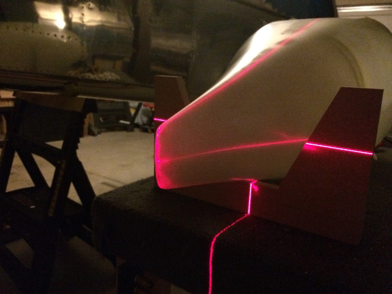
I didn't do a fantastic job of documenting via pictures.  I took random pictures throughout the process but often when I get in the zone of building I just push forward.  Below are some pictures of the process.  Of importance is using Jacks, lasers and a high quality capacitance level such as this to get everything in level flight mode.  I'm not a tool snob but the MD Smart Tool is the most precise, if you're not precise on the leveling you could be off by quite a bit at the end points.  This entire process is spent leveling the plane up, drawing lines on the floor and making everything orient in the way shown below;

Understanding the orientation you work to get these things to stay in place using duct tape, blocks or whatever you have at your disposal.  Some people have made a jig type thing to hold them.  I did something similar but if I had to do it over I would of made something much more robust, may have taken a few hours but would of paid off in the end.


I guess one thing you don't really think about with wheel pants are the gear fairings.  Apparently these have a greater reduction in drag than the wheel pants themselves and you want to get them positioned correctly.  The plans do a good job at walking you through this and you end up using string and taking measurements to get these in.


The intersect pieces I decided to mold into the pants themselves.  This should give a cleaner look in the end but it takes a bit of time and effort.  You'll want to do an overlap and build up about "1/8 - "1/4 on the forward end so air doesn't get trapped on the back piece and rip it off.

Nose

Compared to the mains the nose was a bit easier.  Could be that I had the 35 or so hours of practice with the mains but really the hardest part of the nose was getting the two halves to fit together correctly.  That took a bit of time and in the end used some blue tape on the flange and fit the top over checking with a laser and marking the cuts.  Then slowly sanded it until I was happy with it.  A few other things I did was I waited to final cut the tire opening until they were fitted oh and I followed the instructions with tapping and screwing to get the fit right. Alignment wasn't the challenging since I just show a laser down the center of the plane and did my alignment off that.

I did botch up my standoffs because my drill press struggled to do the holes.  Instead of getting new blanks from Vans and starting over I ordered some CNC'd ones that are literally perfect.


Again didn't do a great job of tracking the progress with pictures.  As you see above a lot of the time I was doing this in the middle of the night and just working through what I could. As with all fiberglass work you'll spend time finishing these pieces.  I used micro to fill in any imperfections and I did skim coats to fill suspected pin holes.  Takes a lot of time sanding, trimming, sanding some more...  The end result of all this fun is shown below.  Glad for it to be done and looking forward to working on the Air-conditioning and some other odds and ends while I wait on the Engine.


Sunday, July 23, 2017

Jacks & Lasers

Not done with fiberglass fun quite yet I decided to tackle the wheel pants and fairings while I wait on the engine and prop. There's a bit of a problem though that it requires you to lift the wheels off the ground and level the plane, as it would be in flight.  Problem is my factory floor isn't level so when I tried to do this with a few saw horses and shims I quickly found out that wasn't going to work.

I began to look for solutions and came across this VAF thread and this build log post.  The concept is fairly easy in that you take a bottle jack and mount it to some sort of base with uprights to keep it from falling over.  For the top you mount something that will help disperse the weight and prevent the jack from shooting through your plane like this....


I would love to have welded up a base and may plan on doing that at a later date but for now I was trying to go as simple as possible. Cost wise these ran just over $100 with a majority of it going to the $46 jacks themselves.  It only took a few hours to put together as well, most of that time being spent cutting and flattening the ends of the uprights.  I did this in a vice and finished up with a hammer.  Then ran them through the band saw and took any burrs off the ends with a grinder.


For the tops I also went pretty simple.  I drilled a hole about halfway through a 2x4 and then screwed that to a flat top piece.  Then I covered it all with carpet and it just sits on top of the jack.  It's secure enough that it's not going to fall off and loose enough that it can shift around a bit.  I bought the last two jacks they had at the store so once is orange and one is red. On the bright sight if I'm working with someone on jacking the plane up I can easily identify which jack to mess with...

Plane Jacks
 It's important for the wheel pants to be inline, leveled and at the right angles.  I was trying to do this with squares, string and levelers and having a hard time.  I decided to pick up a cheap $60 laser leveler and it's helped make the progress a lot easier.  I hadn't used one of these in the past so still learning about them but they seem to be a great tool for this step so far.