Firewall
Per the plans the RV-10 uses a single layer stainless steel firewall with aluminium fittings. This has been shown to melt fairly quick in the event of an engine fire and once your fittings melt then all that smoke ends up in the cabin. For you non-pilots that's a very bad thing....
Solutions have been discussed over on the
VAF forum and Dan Horton has not only come up with a great solution but has provided pictures and test results to back his findings. The idea is that doing a little more to the firewall will slow any fire as well as help keep heat out of the cabin during normal flight.
His suggestion is what I went with was to cover the engine side of the firewall with 1/8th inch Fiberfrax and then cover that with some stainless steel foil. Lastly replace all the fittings with stainless steel versions, secure with stainless steel rivets and caulk seams and edges with 3M Fire Barrier 2000+. Here are his pictures.
 |
| General concept |
 |
| Since the SS Foil comes in 24inch wide rolls this is how you deal with the center seem. |
This was a lot easier than I anticipated, it's a bit of a struggle to work with the Foil but I was able to get it somewhat decent looking. The worst part by far is the ugliness of my caulking but going for more functionality on this one. I should also note that I used a thin layer of the 3M caulking as an adhesive, relying mostly on the fittings and the caulking to hold it down. If it starts pulling at a later day I can add some SS Rivets fairly easily.
 |
| Bare SS Firewall |
 |
| Layer of Fiberfrax with 3M 2000+ applied. |
I would say I'm 95% complete with the firewall. I'm waiting on a back-ordered grommet and some nutplates to finish up the control cable area and to attach the oil cooler. When I get my engine mount I will mark the locations and actually remove the Fiberfrax and Foil from the attachment points. This will allow me to attach the mount directly to the original firewall as designed. I will then apply additional 3M 2000+ around these points as well as any additional fittings I might attach later.
I also decided against putting any type of foam insulation on the cabin side of the firewall. May sound a bit strange since I'm putting a lot of insulation in the plane, but this has less to do with sound reduction and more to keep the heat/cold in, especially since I'm putting an Air Conditioning in the plane. I'm also banking that the Fiber/Foil bit helps keep the heat out so my feat don't burn up while flying... and I feel keeping foam away from the firewall will help keep my feet from literally burning in the case of an actual fire, or from passing out to the smoke that I witnessed when I putting a blowtorch to the material.
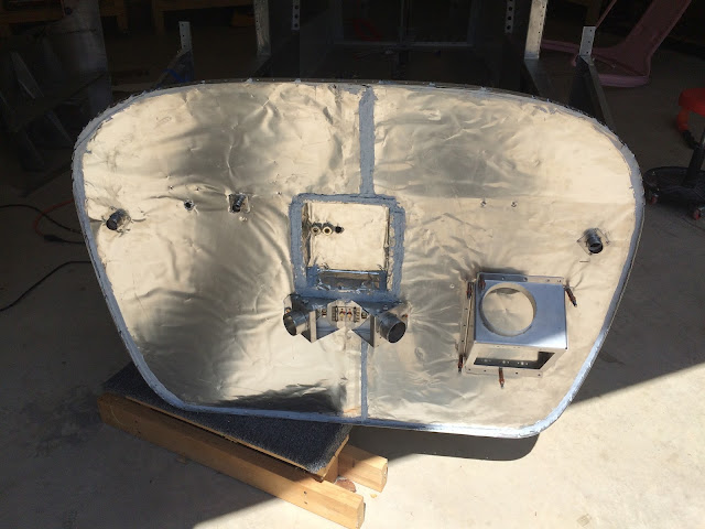 |
| Mostly finished. |
Tunnel
(Update: When I started working through Section 39 and installing the control rods it became obvious I was having clearance issues with my below packets installed. Concerned about having the controls hang up I decided to scratch what I described below and leave the entire tunnel area bare. If later down the road I begin to have 'Hot Tunnel' issues I will go back through and figure something out. My hope is between the firewall side heat shielding, using stainless steel attachments and the new outward facing exhaust that I won't encounter any issues. Only time will tell...)
In earlier kits there was a problem with the center area of the plane, or what's called the tunnel getting extremely hot. This actually lead to Vans putting out a
Service Bulletin. Their solution talks about adding insulation or redirecting some airflow.
For my build my additional firewall work, sealing around the fittings and using all SS attachments 'should' help keep tunnel heat to a minimum. I've decided against putting anything that will burn or give off toxic gas, for the same reason I'm not putting foam against the FW. I've also heard that the exhaust system for the RV-10 has changed to direct heat out sideways now versus down the middle of the plane. In the event that this becomes a problem once I start flying then I will work to solve it then.
Aft of the spar in the tunnel I went ahead and used a method of insulation that I'm comfortable with. It's a bit of a hybrid with what people have used and wasn't all that difficult. I essentially encased a layer of Fiberfrax and Foam in a Stainless Steel Foil pouch. This is the same technique I use to smoke ribs and they turn out fantastic, so why wouldn't that work on an airplane?..
 |
| Starts like this.... |
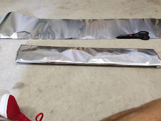 |
| Ends like this, delicious!!! |
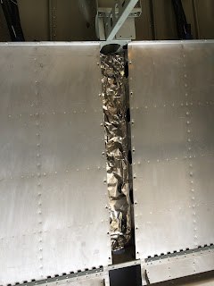 |
| Installed in rear tunnel |
Brake Lines
 |
| Section 36 |
A fairly common deviation from the plans is to not use the 1/4 aluminium tubing for your brake and fuel lines. There are some better options out there and I went with
TS Flightlines for mine. Tom was fantastic helping me work through my order, answered question and was extremely fast to ship out the product. On top of that the lines look great! I was able to knock out the initial part of the install in an evening. The rest of the lines get connected when installing the pedals.
Anytime you deviate from the plans you'll probably encounter an issue here or there. My issue was more with the hole in the gear weldment that the NTP brake line fitting exits was a bit too big and I didn't like the way it sat in there.
My solution was essentially make a washer out of some scrap and wedge that inbetween the bottom skin and the gear weldment. I started with using a 1.5 inch hole saw bit and cut out a couple of blanks. I cleaned the edges of these and used a unibit to put a larger hole in the middle. Because of how the fuselage side skin connects I needed to shave a bit off the 'washer'.
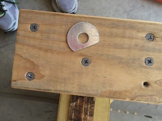 |
| "washer" |
 |
| Final Fit |
 |
| Feels much more secure |
The rest of the task involves running the lines, connecting them to the various NTP fittings and cushion clamps.
 |
| Under front seats |
 |
| Tunnel |
 |
| Cabin side firewall |
This section was extremely quick, I'm guessing not as quick if you have to bend your own lines, flare your connections ect. The rest of the Brake lines (as well as the parking brake) will be installed when I do the pedals.


