Friday, September 28, 2018

Control Cables


The control cables are a basic function of any engine really.  With a constant speed prop I have essentially three cables similar to whats depicted in the plans; throttle, prop, mixture.  What varies on my set up is the routing, mounting and lengths.  The main culprits are my tunnel mounted throttle quadrant, forward facing fuel servo and the air conditioning system. Each of these changes the cable lengths and in the case of the mixture the mounting bracket.

For the cables I went with California Push-Pull based on a number of referrals.  Here are some basic things I learned about control cables.  The point where the cable is hard mounted to a structure is called the 'bulkhead'.  Then there is the 'throw' which is the distance the threaded ends will move.  In my case and most other builders I picked a 2.25" throw.  Meaning the two working ends will essentially shift back and forth that much once connected to whatever you're connecting it to.  That throw will give you another measurement between the bulkhead and the swivel support tube to include the threaded end at mid-travel.... All clear??  Wasn't for me even after reviewing the measuring guide.

Some items I had to mentally digest was that whatever your cabin side bulkhead to mid-travel threaded end measurement was should be somewhat similar on the working side. So on a 2.25" throw cable you couldn't have the cabin side be 6" and the throttle side be 10".  Unless maybe if you start threading extensions on at one end.  Also not every item has the same move distance on the working end.  For me the throttle matched my lever movement, but prop and mixture were about half. From a working perspective pushing full forward on all three levers results in full throttle, full props and full rich on the mixture.  If I pulled everything back the throttle comes all the way back but the prop and mixture level stop just over halfway but they're at their limits.

Full Throttle, Props, Mixture

All Back
The last item deals with the measurements, after all my conversations with David at Push-Pull I thought the measurement for length was bulkhead to bulkhead, but it's from threaded tip to threaded tip.  I spend A LOT of time doing the measurements, double and triple checking so I was surprised that my cables were about 10" too short when trying to install them. Realizing the mistake I talked to David and ordered a new set.  The good news is I talked to my buddy Mike who's building an RV-10 and he's going to be able to use them, but they'll have to be shortened first.  My final 'new' cable lengths are-

176-vtt-2.25 93"
176-vtt-2.25 72"
176-vtt-2.25 74"

With my new cables they were able to be installed and were spot on for length. It takes some tweaking but I was able to get the new ones installed and routed fairly easy.  Given these are thicker diameter than stock Vans ones I had to do some drilling out on my pass-throughs, brackets and used bigger adel clips.

Speaking of brackets I did have to make a new bracket to mount the Mixture cable.  The stock would have had it something like 14" back and adding a bunch of threaded extensions doesn't sound like a good idea.  I had previously worked up a bracket that mounted on the bottom of the sump but that really didn't work out.  This bracket made the bulkhead within 2" of the rod end, which was an issue after learning the above.  I decided to wait until I got my new cables and then retroactively work through a bracket. Now if you're really good at steel work then you should try and do something like Larry did on his fantastic build shown here.  He came up with a steel bracket that replaces the stock bracket that mounts on the bottom of the sump and ends up moving throttle and mixture to a single side.  Given I had an issue with even understanding how these cables work I decided to utilize the stock bracket and fabricate something just for the mixture.

I ended up not fabricating anything but rather re-purposing an already powder coated steel hinge.  It's original intent was to be installed in the wing, which I had done, however replaced it with the servo bracket so had it just laying around. I went through several ideas but decided to just keep it as simple as possible and make some bigger holes in it and hang it off one of the elbow screws off the bottom of the sump. Hard to really see it in the picture but I had to slightly bend it to accommodate an upward angle.  The back of the piece also prevents any serious movement as well.  Maybe I'll do some safety wire just in case.


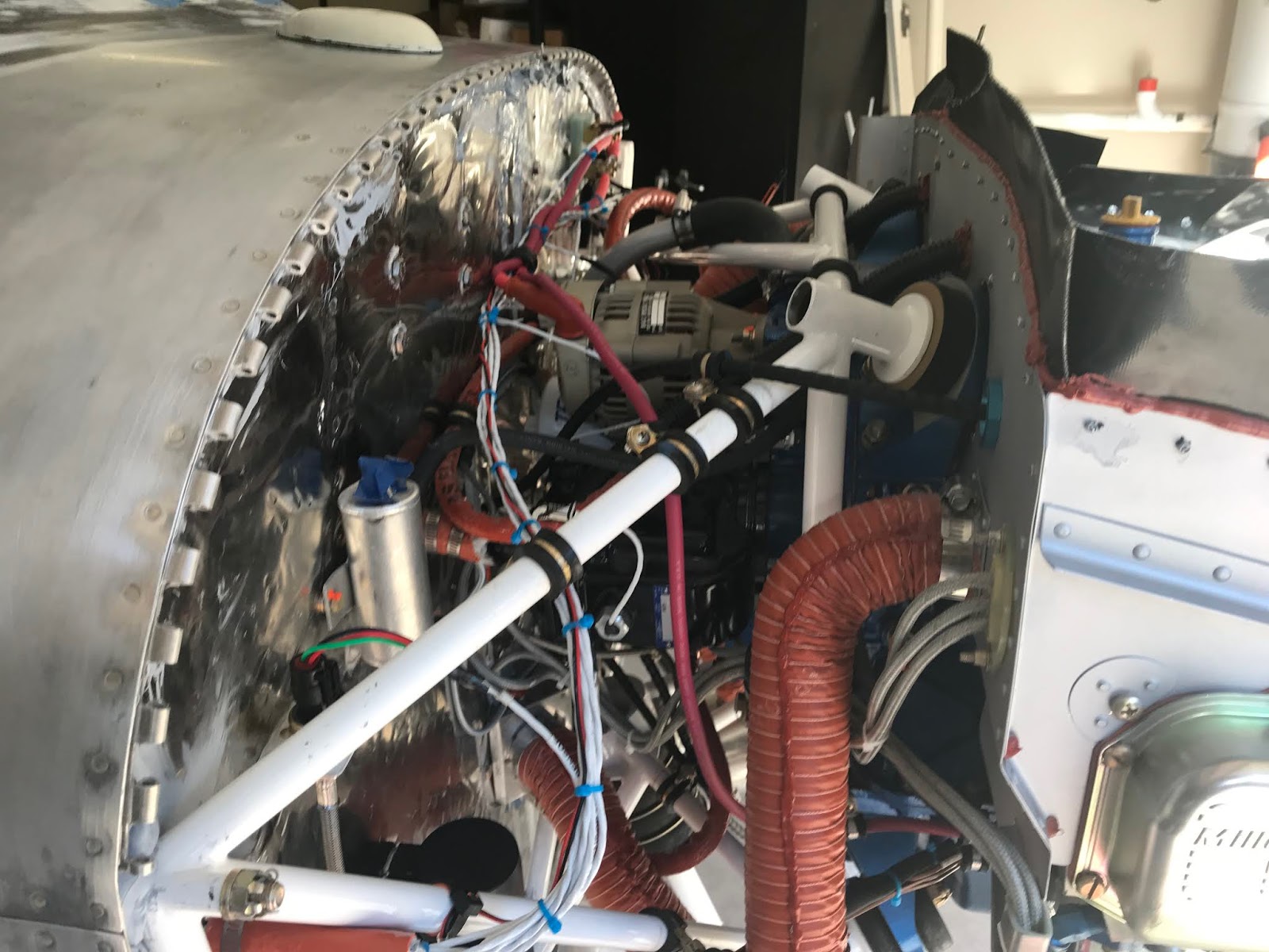
Here are several other pictures showing the Prop and Throttle runs and how I have them aligned.  Because of the AC the prop run has to go over the engine and with the forward mounted fuel servo had to reclock the throttle a bit.  All seems to work out though.


Last picture might be a hard to see, but the lines follow a fairly solid path to the per plans firewall breaks.  Like with all these firewall penetrations I used some 3M fire barrier to fill in the gaps.


Friday, September 14, 2018

Antennas


Installations of the antennas was bumped to the top of my punch list after I was told that I shouldn't power up the avionics without them. I was going to push this off until I had the wings on and what not but instead I decided to go ahead and do it.  This will allow me to test out things in my driveway, so maybe it's best that way.

I'm not sure I realized just how many antennas I was going to need to mount all over the plane.  It's very much dependent on what you're throwing in there and since I'm doing a full glass panel with several redundant components I knew I was going to need to do some placement planning. For my set up I needed the following antennas; 2 for radios, 1 for ADSB, 3 GPS pucks, NAV, a magnetometer and then of course on for the ELT.  That's 9 antennas that I had to figure out where and how to mount.  There's certain spacing and installation parameters you need to consider.  I originally wanted to shove most everything in the tail minus the NAV antenna that's out in the right wingtip. I have to wait until the wings are on to install the NAV and I'm still debating on how and where to install the ELT antenna, so I'll do those later.

Doublers

Obviously when you install antennas you end up cutting up to 3/4 inch holes into the airplane skins.  Doublers are typically suggested but not required.  My 172 had GPS pucks with no doublers and never had an issue.  But since I tend to overbuild so I wanted to go ahead with doublers for all antennas.  Making them wasn't an issue, for the GPS pucks I actually had a factory made one that I was able to replicate, and then using some ideas online make them for the rest.

Attaching them is a different story.  I've seen some elaborate rivet patterns which frankly look like drilling, dimpling and two person rivet driving.  I read that the rivets actually help with the strength, but that guy was using metal the same thickness of the skins (thin).  I decided to go thicker metal and use 3M aviation two part epoxy to secure in place. I also went ahead and primed the exposed side.  In the end these things aren't going anywhere, the skin is thicker and it adds to the rigidity.

Here's a picture showing my GPS puck doublers.  The one on the left is from Garmin, the other two I made.

Comm antennas

Not surprisingly there are a number of strong options on how and where to place your comm antennas.  The two schools of thought is you should put one on top of your tailcone and the other on the bottom.  This would prevent any shadowing or possibility of dropped comms.  Then you have the other group that prefers to mount both antennas on the bottom, either the front or read seats.  The idea is shorter runs, a bit out of the way and suitable.  I've read plenty from both sides and my conclusion is people have been successful installing either way so I needed to pick what will work best for me.  My tailcone is pretty cramped so I decided under the back seats was the way to go.

First I needed some way to access these.  I had seen people use the Vans wing access panels but those are pretty big.  All I needed was enough space to get my hand in to do the initial installation and any future maintenance.  Luckily I have baby hands so it will fit between the ribs fairly easy.  However you don't want a gaping hole beneath your seats and still need a way to cover it.  I just went head and essentially made a door on some hinges.


For this doubler I didn't want it over the rib piece.  So decided to go ahead and epoxy the piece in there first and then drill the mounting holes.  This saved me the trouble of trying to match holes, just slap it on and let it cure.

Once it was cured I drilled out the holes based on the gasket I received and used drawn lines to center.  Then it's just a matter of bolting on the CI 122 VHF comm antennas, one each side.  Two person job to tighten and to torque I had to do about 8 inches of extensions to reach the nuts.


ADSB

Hmm, I didn't take any pictures but I went with the CI-105 and I mounted it under the copilot seat, basically centered and making sure it's not hitting any brake or fuel lines.  I also made a doubler specific for this antenna.

GPS

I have two GA 56's for the G3X and G5 and a much larger GA 35 for the GTN 650.  Using the doublers pictured above I installed one behind the firewall but in front of the windscreen.  For that one I used the stock Garmin backing plate and didn't epoxy.  Mainly out of laziness, I didn't want to try to mess with that stuff crawled under the panel.  Interesting note I used a antenna I got off Ebay for my 172 that I never ended up using.  It's dirty looking but only cost maybe $40.


The last two I installed behind the cabin on the top of the tailcone.  I had to wait to talk to Bill at Airflow Systems to ensure this position wasn't going to interfere with the AC system I haven't fully installed yet.   It was easy to work with since the top skin isn't riveted down, just had to mark it and then match drill the holes, epoxy up and after cured clean the holes and bolt them on.


Magnetometer

I can't even pronounce what this is.  It's basically an electronic compass that needs to be clear of all sorts of things while limiting what's called the CAN bus down to 40 feet.  Stein did the harness and really the only place to put this is in the tailcone.  Also it needs to be level, within a few degrees of the plane heading and away from all sorts of things.  I saw all sorts of elaborate things hanging off the top of the tailcone but given that would be fairly close to my AC and lots of spinning metal I decided to make some type of shelve to span across the longerons.  That would ensure it's level in flight and hopefully give enough space to not run into interference.   I haven't tested this so the jury is still out.

What I did was make a tiny shelve across two aluminium angles to mount behind between the 2nd and 3rd compartments in the tail.  I do this I had to make part of it removable that I can rivet post testing.  I'll also epoxy it down to the longerons vs drilling holes to hold it in place.  Again going to do this after all the testing is done.


Short post for the amount of work that went into all this.  When it cools off a bit I'm going to go ahead and pull the plane to the driveway and start doing some testing and calibration... actually I'll probably get impatient and start messing with it.

Saturday, September 8, 2018

Happy 3rd Birthday! Hangar move punch list

Happy 3rd Birthday!

3 years and 1,115 hours into this project as of today! I hope to have the plane moved out of my garage and into the hangar within the next 6 months.  And then if all goes well, flying by this summer.  As exciting as that all is there is still quite a bit of heavy lifting before I get to that point.  I want to ensure I have as much done on the plane as possible before making the move.  I started to split my punch list into two categories; pre-hanger move and final assembly.

Hangar move punch list 

When it comes to the punch list there are some obvious items that can't be complete prior to the move.  For example I can't do the control rigging or wire up the landing lights until the wings are on.  I've used lists throughout the process to keep things straight, especially when working on items that don't have specific plans.  Here are all the current items I plan to have complete prior to moving.  Some are small few hour tasks, some are more in-depth and will require a bit more then a day or two to complete. In those cases I split them out into even more subtasks.   Here's what I'm looking at-

  • Wire ACS Starter switch
  • Wire Mag ½
  • Wire Cowl Flaps
  • Wire Door Sensors
  • 44-2- Bevel lower corners
    • 44-4 Install K1100-08 nutplates
  • Mount flaps Position sensor & run wire
  • Wire Headset Jacks
  • Wire USB Chargers
  • Control sticks
    • Install leather wrapping
    • Mount sticks
    • Wire Pilot/CoPilot – DB connectors
  • Mount Antennas
    • Comm #1 Comm #2
    • Nav #1 – Bob Archer Wingtip (Run cable)
    • G3X GPS – GA56 Tail
    • GTN 650 GPS – GA 35 Tail
    • G5 GPS – GA 56 Front
    • Transponder
  • Magnometer install
  • Engine Control Cables
  • Fabricate new Mix bracket.
  • Install Interior Nutplates
  • Refinish all plastic panels Interior
  • Air-condition
    • Mount evaporator to shelf
    • Crimp hose to fittings
    • Install return airflow
    • Install cabin flood and overhead duct
    • Wiring rotary switch
    • Wire Panel to Evaporator
  • Secure Aft FWD Skin and backing strip
  • Review and collect parts for final assembly
Posts without pictures aren't as fun so I decided to include a picture of my panel all powered up.  I took this a few days ago, however nothing is really going to function until I add the antennas and magnetometer.  I am slightly concerns though because when talking to Stein prior to ordering my antennas he mentioned that he's had problems with the transponders blowing a fuse or something when they're powered up without an antenna.  I really hope this isn't the case but to be safe moving forward I disabled all the avionic breakers in the VPX.