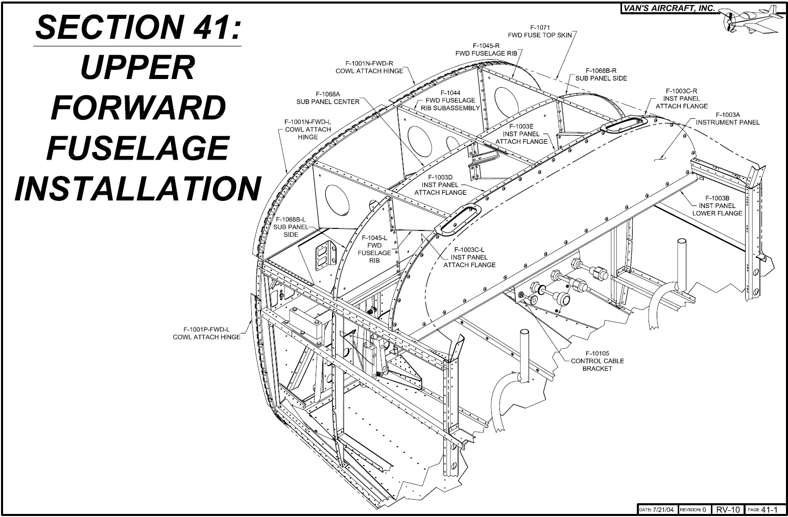
Upper Forward Fuselage Installation
 |
| Section 41 |
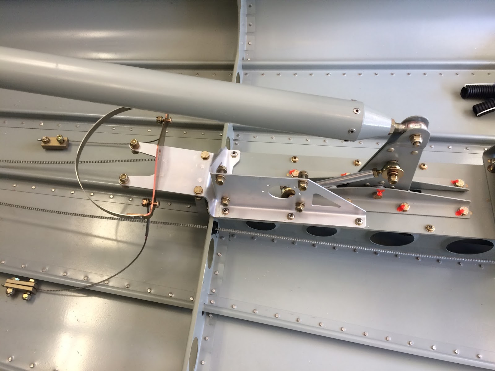
The plans give you two options for Section 41. There's the picture above meant for a builder using vernier style control cables and then a Section 41Q for someone using the standard throttle quadrant. I'm doing neither and I'll be using the Aerosport
Quad Arm Rest which relocates the quadrant in a much more convenient location. So it really didn't matter which section I was going with as the attachment was the same in both sections.
I started this section not following the plans at all but instead starting putting access panels back on. The flap and seat covers and the tunnel areas I'm done with for now so for some rigidity while I'm climbing all over I wanted to go ahead and attach these. I even put in all the screws, you save a few minutes if you don't but would rather have everything in place as it should be.
 |
| Access panels. |
Didn't take a lot of pictures because the attachment part isn't anything that hasn't been shown. Just follow the directions and rivet everything up. I had to use larger rivets when attaching to the firewall because I increased the depth of the firewall by about 1/4 inch or so and needed to compensate. A rivet gauge is handy for this type of thing but at this point in the build you should be able to eye ball it.
Once it's all rivets up you start to work on the hinge attachments which will later be used to attach the engine cowls. It starts with fabricating some shims that will be spaces between the flanges and the hinges. I used some left over trim pieces I had from the empennage kit and got them cut to spec. Then you do the same with the hinges cutting to the size you need.
Then it's time to cleco to the fuselage and this is where I ran into some problems... My earlier adventure of caulking 3M 2000 fire sealant was preventing me from getting a proper seating of these pieces. I remember thinking about this as I was doing but for whatever reason thought the hinge went between the flanges and the skin... not the case.
 |
| Not going to work. |
I tried several things to clear the area and the best and easiest was to use a razor blade and cut about 1/8th area out where the hinges had to go and then remove the material and clean it up a bit. After that everything worked out and I started the process of getting everything in and match drilling.
After the picture above I did some reading and found out there were builders who had some issues with the small bottom hinges eyelets breaking. Well that's not a good thing and the resulting solutions deal with getting camlocs or using a piece of aluminium and nut plates on the bottom. I had to backtrack a bit and drill out the hinges I had previously installed. I found on my project plan notes that this was one of the items to modify, but I was in the zone on this section and hadn't considered it.
The solution is to fabricate a piece of aluminium with 4 #8 nutplates attached. To do this you can use some .63 or so scrap and size it basically to the same size as the hinge piece. Then match drill using the existing shim as a guide, clean and countersink the aft holes. Then space out 4 #8 nutplates across, countersink and rivit those holes and clean up any edges.
What I did though was use the a lower console piece typically used to support the various switches of a control panel. This came completed with my QB kit. Going with the Aerosport EFIS panel option though a majority of this piece won't be used. I will use it later to make a mounting bracket for the Carbon Fiber panel but outside of that you can cannibalize it into whatever you need.
 |
| Switch Bar (Not in installed location) |
 |
| Cut lines drawn out to incorporate 2 existing nutplates |
 |
| Edges Cleaned |
 |
| Match drill to the shim |
Once everything was cleco'd up you removed it all, debured, countersunk or dimpled the pieces. Then it's just a matter of reattaching and riveting to the skin and firewall flanges. I was able to use my pneumatic squeezer (favorite tool) to set all the rivets. Will have to later reapply 3M 2000+ fire barrier, but this time going to wait until I attach the engine mount, because I'll be removing material as well when I do that.
 |
| Nutplate bracket |
 |
| Final |
What Next?
There are times (many) during this project that confusion sets in and you're not sure what exactly your supposed to do next. The default is to always reference and follow the plans in order. However the next step is to install the rear seats but since I'm going to use some aftermarket seats so I can scratch that section for now. The one after that is the cabin top which I actually started this summer and it's ready to get placed back on whenever... However before I secure the cabin top down I want to make sure I have certain additional/non-plan items completed first.
These non-plan items are all the niceties and extras as a builder you can decide to include. In my case it's things like Air Conditioning, 3-axis autopilot, full blown leather interior and a fancy suite of avionics. Because I have conduit run and most these items are small enough they can be installed with the cabin top and doors. However some are just easier to install with everything opened up right now, ie the Air Conditioning, things in the tail cone, ect. On top of that each of these options need to be researched and understood and they'll increase your projects timeline and cost.
So close to wrapping up with the fuselage and only having the wingtips to complete before working on the finishing kit I'm going to have to spend some time working though the next phase of building. This involves continual research, updating my project plan and staging out what I need to buy and when. Some things are good to wait till you actually need to before ordering, makes no sense to buy a bunch of avionics and having them sitting on a shelf for a year or two. And who knows, by the time I order my engine maybe six cylinder
P-Mag/E-mags will be out!


